
Methods And Apparatus For Reducing Stress Variations in Glass Sheets Produced From a Glass Ribbon.

a technology of stress variation and glass ribbon, which is applied in the field of glass sheet manufacturing, can solve the problems of substantial number of defective (rejected) displays, changes in vacuumed-flat shape of glass sub-pieces,

Active Publication Date: 2010-02-25
CORNING INC
View PDF15 Cites 40 Cited by
  • Summary
  • Abstract
  • Description
  • Claims
  • Application Information

AI Technical Summary

Benefits of technology

[0010]In certain embodiments of the invention, step (c) reduces movement in a horizontal direction of at least a portion of the ribbon's central region (51), said portion being located between the forming assembly (41) and the separating assembly (20). In accordance with these embodiments, the temperature of the glass at said portion can be within the glass' glass transition temperature range. Although not wishing to be bound by any particular theory of operation, it is believed that in this way, variations in the stress levels of glass sheets (11) cut from the ribbon (13) are reduced at at least one location, e.g., along at least one edge of the glass sheet (11).

Problems solved by technology

Such stress relief in general results in changes in the vacuumed-flat shape of the glass sub-pieces, a phenomenon referred to by display manufacturers as “distortion.” Although the amount of shape change is typically quite small, in view of the pixel structures used in modern displays, the distortion resulting from cutting can be large enough to lead to substantial numbers of defective (rejected) displays.
Accordingly, the distortion problem is of substantial concern to display manufacturers and specifications regarding allowable distortion as a result of cutting can be as low as 2 microns or less.

Method used


Image

  • Methods And Apparatus For Reducing Stress Variations in Glass Sheets Produced From a Glass Ribbon.
  • Methods And Apparatus For Reducing Stress Variations in Glass Sheets Produced From a Glass Ribbon.
  • Methods And Apparatus For Reducing Stress Variations in Glass Sheets Produced From a Glass Ribbon.

Examples


Embodiment Construction

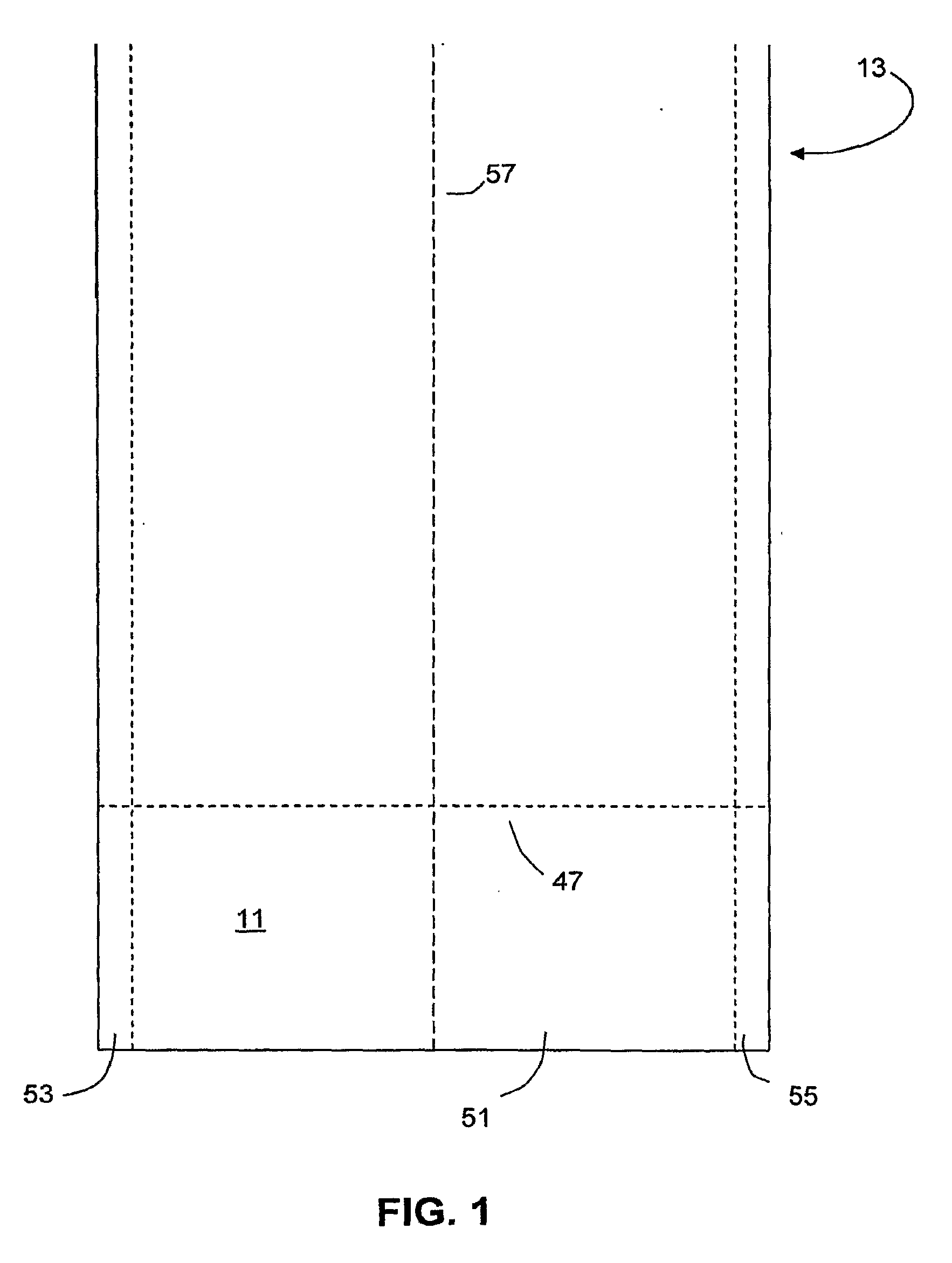
[0024]FIG. 1 shows a representative glass ribbon (13) which comprises a central region (51) (the quality portion of the ribbon) and two edge regions (53),(55) (the non-quality or “bead” portions of the ribbon), which typically will contain a knurled pattern as a result of contact of these regions with one or more edge or pulling rollers. Also shown in this figure are the ribbon's centerline (57) and separation line (47) at which an individual glass sheet (11) is removed from the ribbon.

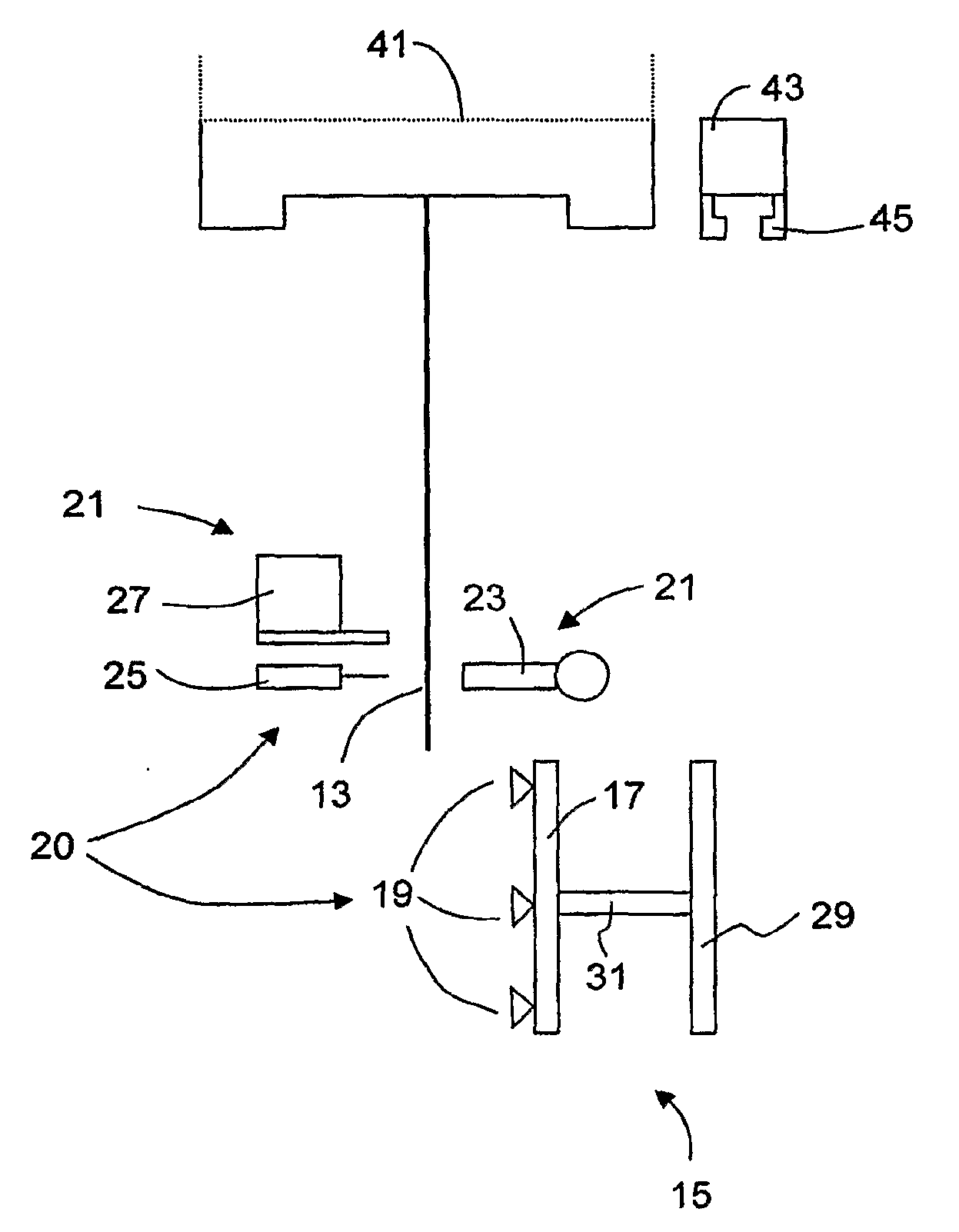
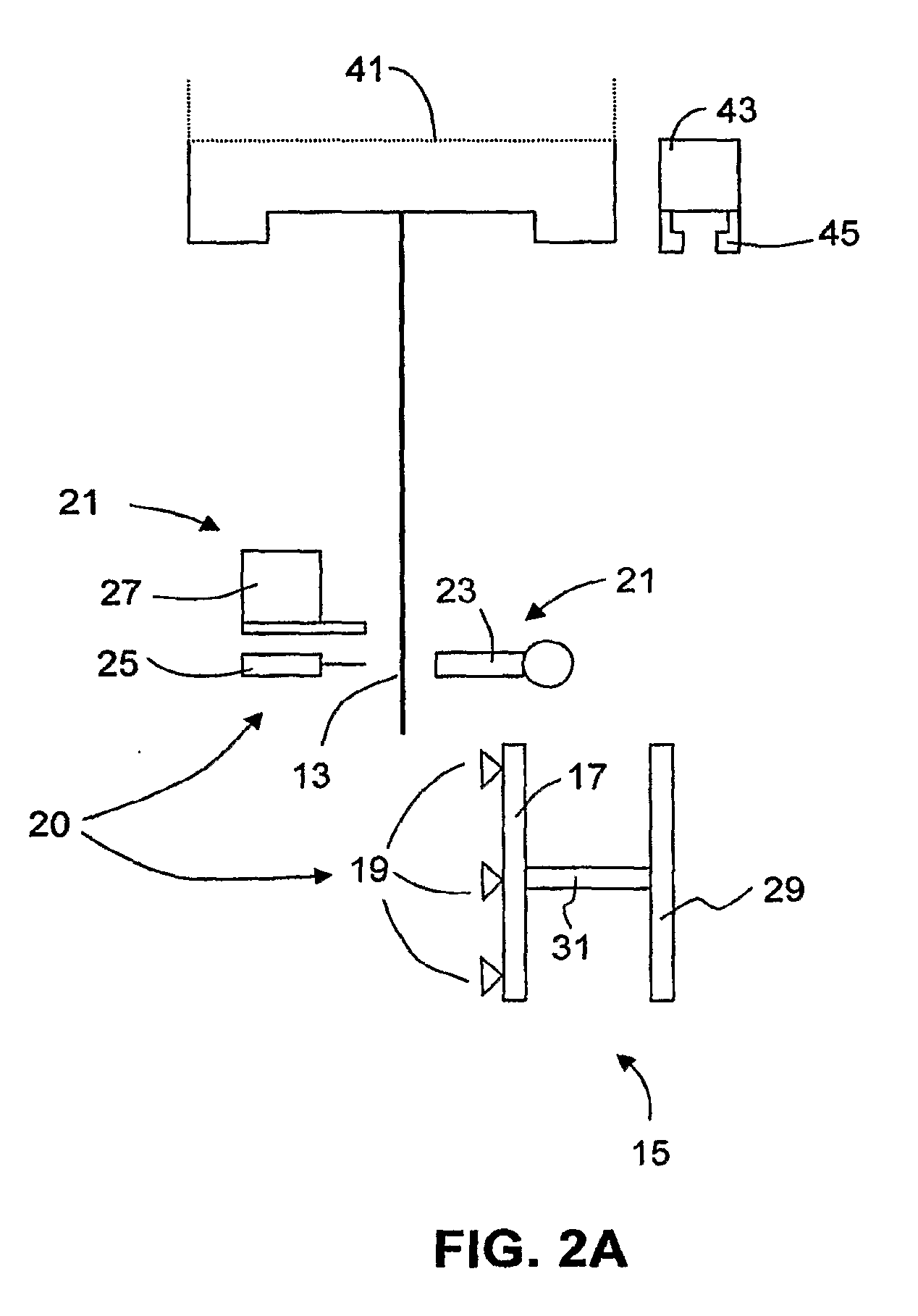
[0025]FIGS. 2A, 2B, and 2C show a suitable separating assembly (20) which can be used in accordance with the present invention to remove individual glass sheets (11) from ribbon (13). This assembly is of the type disclosed in commonly-assigned Andrewlavage, Jr., U.S. Pat. No. 6,616,025, the contents of which are incorporated herein by reference. Other equipment having different configurations and functionalities can, of course, be used in the practice of the invention if desired.

[0026]In each of FIGS....


PUM

PropertyMeasurementUnit
Temperatureaaaaaaaaaa
Glass transition temperatureaaaaaaaaaa
Stress optical coefficientaaaaaaaaaa

Abstract

In a vertical glass drawing process, an edge guiding assembly (33) located between a glass forming apparatus (41) and a glass sheet separating apparatus (20) reduces horizontal motion of the glass ribbon (13) from which the glass sheets (11) are removed and results in the reduction of the difference in stress levels between the top and bottom edges of a glass sheet (11) made by the process. The edge guiding assembly also provides a reduction of the variation of stress levels between successive sheets of glass made by the vertical drawing process.

Description

I. FIELD OF THE INVENTION[0001]This invention relates to the manufacture of glass sheets such as the glass sheets used as substrates in display devices such as liquid crystal displays (LCDs). More particularly, the invention relates to methods for reducing the amount of distortion which glass substrates exhibit when cut into parts during, for example, the manufacture of such displays.II. BACKGROUND OF THE INVENTION[0002]Display devices are used in a variety of applications. For example, thin film transistor liquid crystal displays (TFT-LCDs) are used in notebook computers, flat panel desktop monitors, LCD televisions, and Internet and communication devices, to name only a few.[0003]Many display devices, such as TFT-LCD panels and organic light-emitting diode (OLED) panels, are made directly on flat glass sheets (glass substrates). To increase production rates and reduce costs, a typical panel manufacturing process simultaneously produces multiple panels on a single substrate or a su...

Claims


Application Information

Patent Timeline
IPC IPC(8): C03B17/06C03B15/02
CPCC03B17/06B65G2249/04C03B33/0215Y02P40/57C03B33/02
Inventor KIRBY, THOMAS EDWARDDE PAOR, LIAM RUAN
Owner CORNING INC
Learn More