Solar Panel Interconnection System

a technology of interconnection system and solar panel, which is applied in the direction of photovoltaics, electrical devices, and semiconductor devices, can solve the problems of increasing the cost of the cable itself, the total increase of the power, and the loss of power through resistance, so as to achieve the effect of minimizing the total resistive loss, minimizing the length of the cable between the panel and the array, and avoiding the loss of power

Inactive Publication Date: 2010-02-25
CROFT STEVEN THOMAS
View PDF5 Cites 21 Cited by
  • Summary
  • Abstract
  • Description
  • Claims
  • Application Information

AI Technical Summary

Benefits of technology

[0023]A feature of the present invention is that when such first and second solar panels are disposed in an array, taps to be connected to each other in any one row or column of the array are always proximate each other thereby advantageously minimizing cable lengths between panels. Accordingly, the total resistive losses due to electrical interconnection cables and also the cost of such cables in the array are also advantageously minimized.

Problems solved by technology

When current flows through any such connector or cable, a voltage drop occurs across such connector or cable and some power is lost through its resistance as dissipated heat.
Although the overall power output the entire array is increased, the increase is less than the sum total of the power of the additional panels due to the increased resistive losses in the longer cables needed for panel interconnection.
Another consideration, in addition to resistive losses incurred through excessive cable lengths, is the cost of the cable itself.
Clearly, should maximum cable lengths for panel to panel interconnection, as in the examples set forth above, be required for a typically sized array the cost of the cable would be significantly increased as compared to adjacent panels having closely disposed junction boxes on the edges thereof.

Method used


Image

  • Solar Panel Interconnection System
  • Solar Panel Interconnection System
  • Solar Panel Interconnection System

Examples


Embodiment Construction

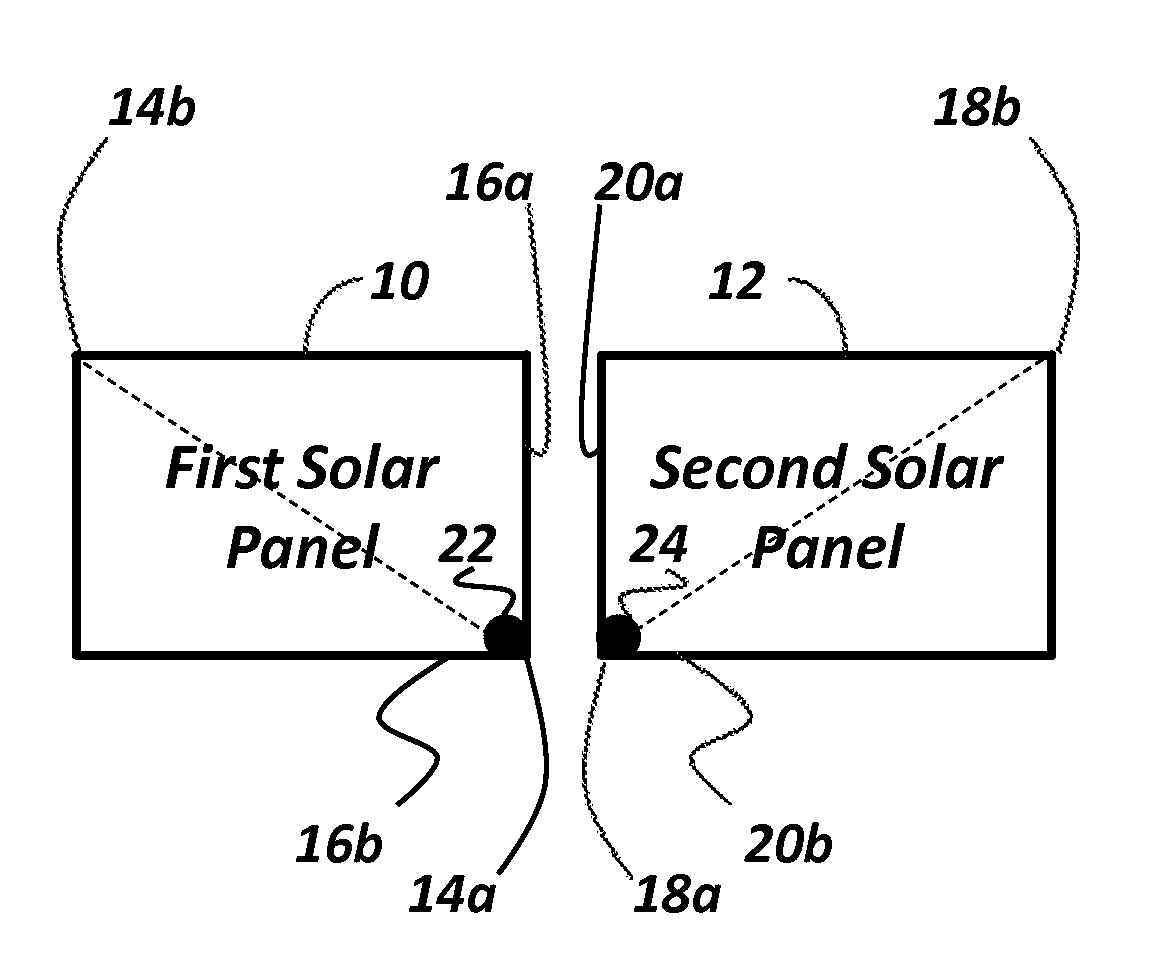
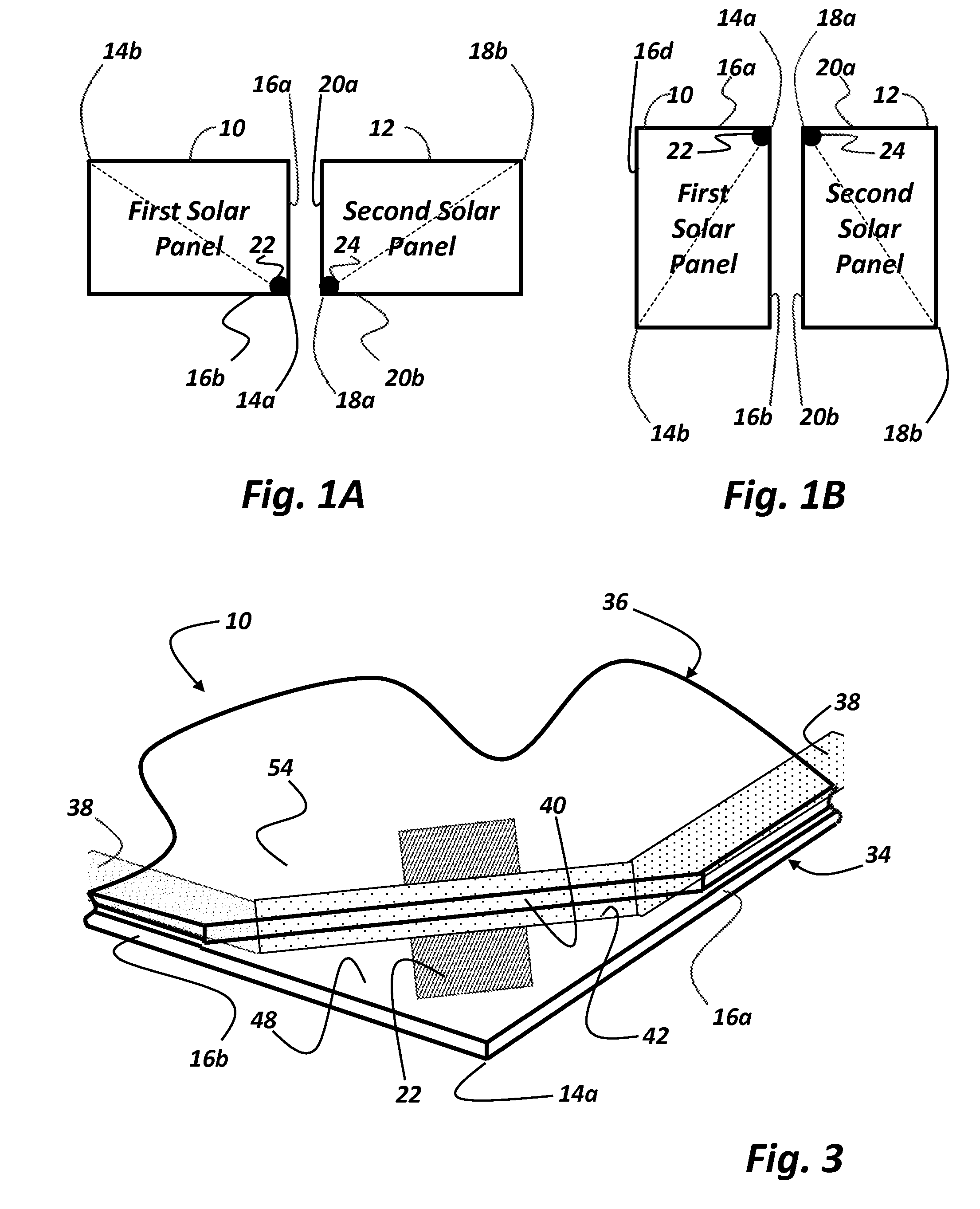
[0031]Referring now to FIGS. 1A-1B, there is shown a first solar panel 10 and a second solar panel 12. The first solar panel 10 has first diagonally opposed corners, 14a, 14b and a first edge 16a and a second edge 16b extending from one of the first diagonally opposed corners 14a, 14b, exemplarily shown herein as corner 14a. Similarly, the second solar panel 12 has second diagonally opposed corners, 18a, 18b and a first edge 20a and a second edge 20b extending from one of the second diagonally opposed corners 18a, 18b, exemplarily shown herein as corner 18a.

[0032]The first solar panel 10 further has a tap 22 disposed thereon at one of the first diagonally opposed corners 14a, 14b from which each of the first edge 16a and the second edge 16b of the first solar panel 10 extends, exemplarily shown herein as corner 14a. Similarly, the second solar panel 12 has a tap 24 disposed thereon at one of the second diagonally opposed corners 18a, 18b, from which each of the first edge 20a and t...


PUM


Abstract

A solar panel interconnection system in which electrical interconnection distance is minimized irrespective of one of landscape or portrait panel orientation includes a first solar panel having first diagonally opposed corners, a first edge, a second edge and a tap to provide electrical connectivity thereto, and a second solar panel having second diagonally opposed corners, a first edge, a second edge and a tap to provide electrical connectivity thereto. The first edge and the second edge of the first solar panel extend from one of the first diagonally opposed corners and the tap on the first solar panel is disposed at the same corner thereof. The first edge and the second edge of the second solar panel extend from one of the second diagonally opposed corners and the tap on the second solar panel is disposed at the same corner thereof. The first solar panel and the second solar panel are disposed with either the first edge of each facing each other, such as in a landscape orientation, or the second edge of each facing each other, such as in a portrait orientation. In either event, the tap on each panel will be proximate each other to minimize electrical interconnection distance.

Description

RELATED APPLICATION DATA[0001]The present application is a continuation-in-part of commonly owned application for Solar-Cell Module with In-laminate Diodes and External-Connection Mechanisms Mounted to Respective Edges, Ser. No. 12 / 121,602, filed May 15, 2008, the specification of which is incorporated herein as if fully set forth.BACKGROUND OF THE INVENTION[0002]1. Field of the Invention[0003]The present invention relates generally to solar panels and more particularly to an interconnection system in which an electrical connection length between adjacent panels during field installation is minimized irrespective of orientation of such panels within an array.[0004]2. Description of the Related Art[0005]A typical solar panel includes a plurality of individual solar cells aggregated and electrically interconnected so that the electrical current developed by each individual cell in response to solar energy incident thereon is ultimately conducted to a current collector node, which may ...

Claims


Application Information

Patent Timeline
Patent Type & Authority Applications(United States)
IPC IPC(8): H01L31/042
CPCY02E10/50H01L31/05H02S40/36
Inventor CROFT, STEVEN THOMAS
Owner CROFT STEVEN THOMAS
Why Eureka
Try Eureka