Traction device

a technology of traction device and flat belt, which is applied in the direction of driving belt, v-belt, rope and cable for vehicles/pulleys, etc., can solve the problems of relatively high shear of the elastomer material of the flat belt, and achieve the effect of improving the friction and the resistance to wear of the composite rop

Active Publication Date: 2010-02-25
CONTITECH ANTRIEBSSYST
View PDF17 Cites 18 Cited by
  • Summary
  • Abstract
  • Description
  • Claims
  • Application Information

AI Technical Summary

Benefits of technology

[0049]The friction as well as the resistance to wear of the

Problems solved by technology

However, here too, the zone of the force transfer between the traction sheave and the traction means is still significant

Method used


Image

  • Traction device
  • Traction device
  • Traction device

Examples


Embodiment Construction

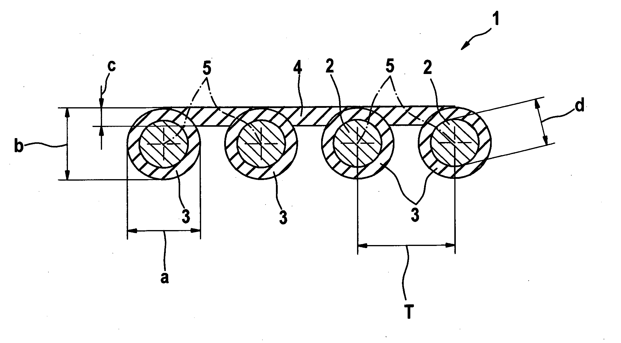
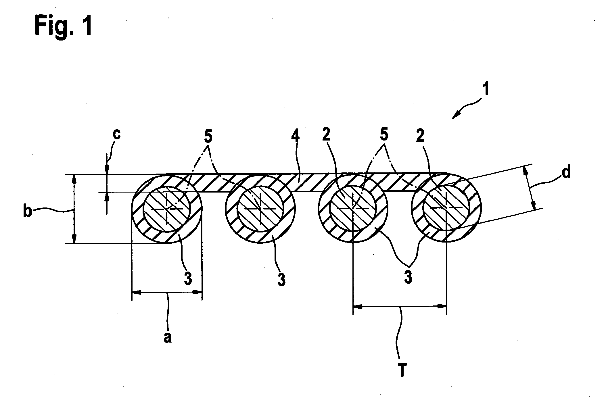
[0055]The composite rope 1, which is shown in cross section in FIG. 1, includes four individual ropes 2 having a diameter (d). Each individual rope 2 is encased with a jacket 3 of elastomer. The individual ropes 2 together with the jacket 3 form a total diameter (a).

[0056]The individual ropes 2 are fixedly connected to each other on one side by a connecting layer 4 having a thickness (c). The connection is generated by vulcanizing together the elastomer jacket 3 with the connecting layer 4 and the individual ropes 2. The connecting layer 4 is arranged on the side of the individual ropes 2 which faces away from the traction sheave (not shown).

[0057]The individual ropes 2 each have a center point 5. The center points 5 of the individual ropes 2 are spaced from each other by a dimension T. The composite rope has a total thickness (b).

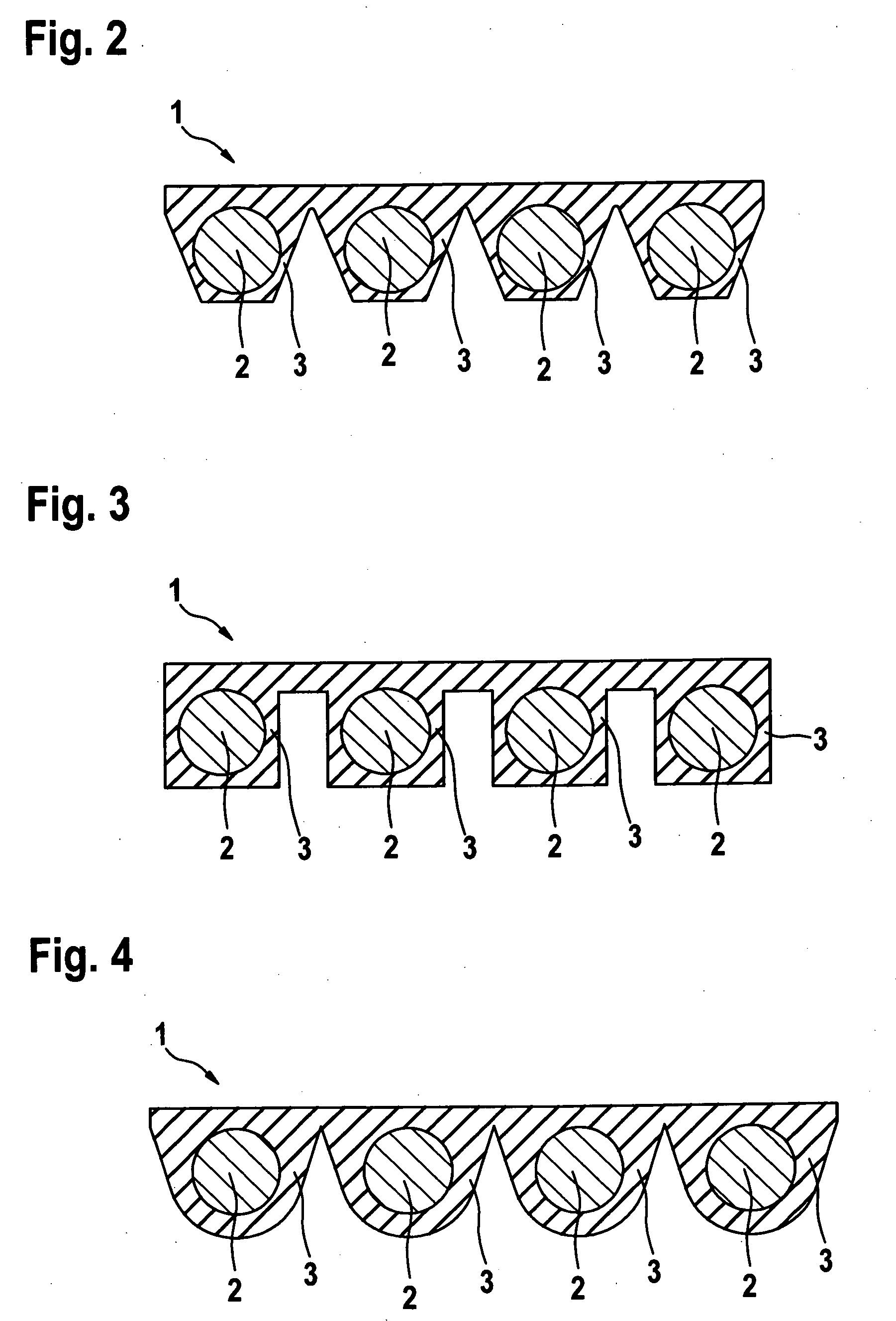
[0058]Composite ropes 1 are shown in FIGS. 2, 3 and 4 wherein the jackets 3 of the individual ropes 2 have a geometry departing from that of a circular sh...


PUM


Abstract

The invention relates to a traction device (1), especially for an elevator system. The traction device (1) is driveable by a traction sheave. The task which is the basis of the invention is to provide a traction device which is simple to manipulate. High tension forces are transferable and the traction device makes possible a drive unit of lesser width compared to the known belt technology. For this purpose, the traction device is configured as a composite rope (1) wherein individual tension carriers (2, 3) are connected to each other via a one-sided elastomer connecting layer (4). The individual tension carriers (2, 3) lie in parallel and are jacketed with elastomeric material. The tension carriers (2, 3) engage in corresponding grooves (13) of the traction sheave (10). The tension carriers (2, 3) engage in the grooves (13) of the traction sheave (10) with at least 25% of their total diameter.

Description

CROSS REFERENCE TO RELATED APPLICATIONS[0001]This application is a continuation application of international patent application PCT / EP 2008 / 053729, filed Mar. 28, 2008, designating the United States and claiming priority from German application 10 2007 021 434.2, filed May 8, 2007, and the entire content of both applications is incorporated herein by reference.FIELD OF THE INVENTION[0002]The invention relates to a traction device especially for an elevator system with the traction device being driven by a traction sheave.BACKGROUND OF THE INVENTION[0003]Traction devices for elevator systems are known per se. Ropes as well as belts are often used and as belts, flat belts, multiple V-ribbed belts or even toothed belts are utilized.[0004]For ropes as traction devices, each individual rope is clearly assigned its own rope groove on the traction sheave. Each rope engages into the corresponding rope groove by at least a portion of its diameter. Each individual rope is an independent tract...

Claims


Application Information

Patent Timeline
IPC IPC(8): F16G1/28F16G1/00B66B11/08F16G1/22
CPCF16G5/20B66B7/062
Inventor GOSER, HUBERT
Owner CONTITECH ANTRIEBSSYST
Why Eureka
Try Eureka