Current detection apparatus

a current detection and apparatus technology, applied in the direction of galvano-magnetic hall-effect devices, magnetic measurements, electric/magnetic means, etc., can solve the problems of increasing the overall conductor resistance, requiring a relatively high level of complication and expenditure, and unable to implement a potential-free measuring operation in the way of that way, so as to increase the resistance of the conductor portion, increase the strength of the output signal, and increase the accuracy

Active Publication Date: 2010-02-25
SEUFFER ROBERT GMBH & CO
View PDF3 Cites 35 Cited by
  • Summary
  • Abstract
  • Description
  • Claims
  • Application Information

AI Technical Summary

Benefits of technology

[0015]A plurality of mutually spaced sensor elements can be arranged on the carrier portion, wherein in the inserted position of the carrier portion in the intermediate space at least one respective sensor element is arranged with respect to the intermediate space on different sides of the multi-part conductor. In that way it is possible to increase the strength of the output signal (measurement signal) from the arrangement, whereby an increase in accuracy is achieved.
[0016]To avoid an increase in the resistance of the conductor portions, the plurality of conductor portions can have a cross-sectional area corresponding

Problems solved by technology

Such a current measurement procedure however suffers from the disadvantage that an additional highly accurate resistor must be incorporated into the circuit of the current to be measured, for a suitable level of accuracy, so that the conduction resistance overall is increased.
A measuring device connected to that resistor for the detection of the applied voltage is moreover at the potential of the line, the current of which is to be measured, so that it is not possible in that way to implement a potential-free

Method used


Image

  • Current detection apparatus
  • Current detection apparatus
  • Current detection apparatus

Examples


first embodiment

[0035]A conductor arrangement of the current detection apparatus according to the invention, in a first embodiment thereof, is described in detail hereinafter.

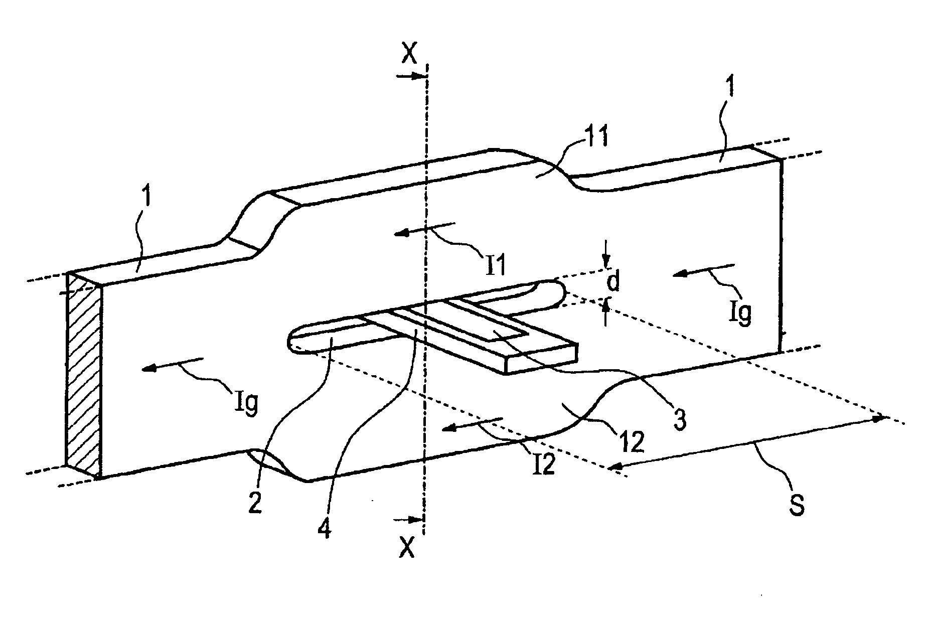
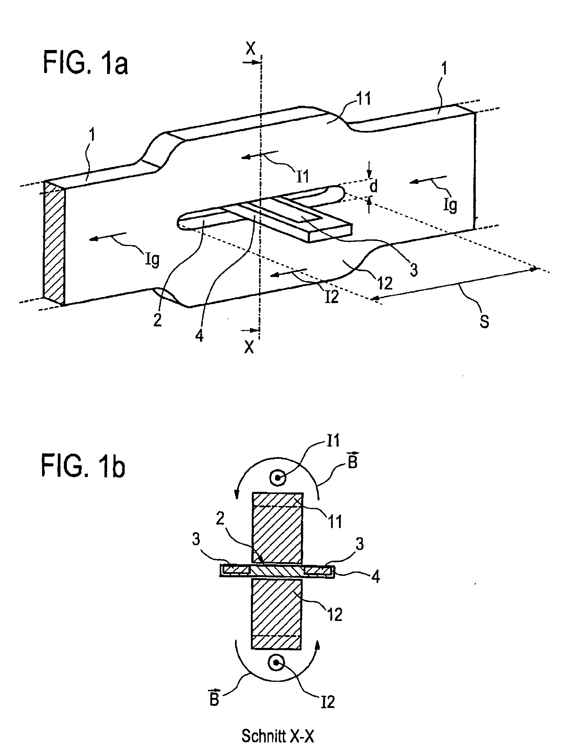
[0036]In detail FIG. 1a shows a conductor 1 in which a current Ig flows from right to left in the Figure. The current Ig is the current to be detected and represents the total current in the conductor arrangement.

[0037]In a predetermined region (predetermined section) S of the conductor 1 the conductor 1 is of a multi-part configuration and in the present case for example is of a two-part configuration so that this forms a first conductor portion 11 and a second conductor portion 12 which are guided in substantially mutually parallel relationship and moreover substantially together involve the same cross-section as the conductor 1. In the predetermined region S of the multi-part configuration of the conductor 1 the first conductor portion 11 and the second conductor portion 12 are mutually spaced by a predetermined spacing d. ...

second embodiment

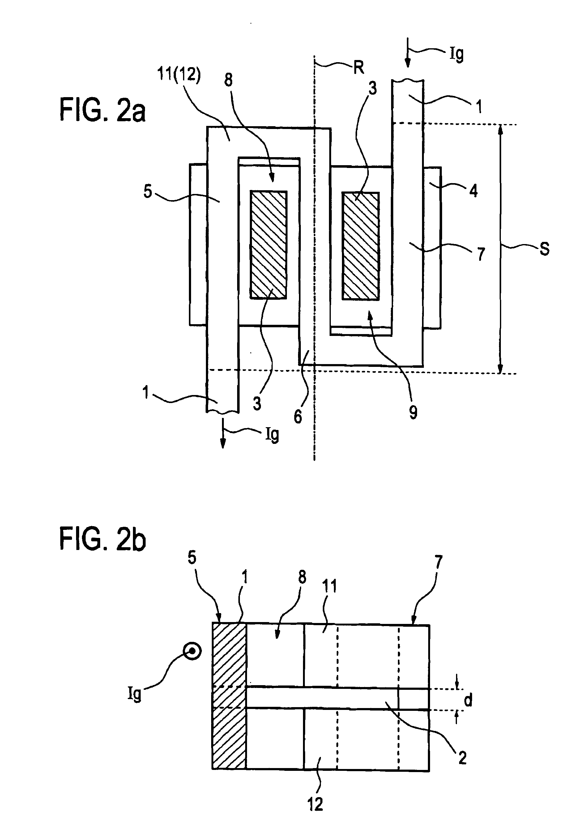
[0054]With reference to FIGS. 2a and 2b, the current detection apparatus according to the present invention will now be described hereinafter.

[0055]In the view in FIG. 2a showing a plan view of the conductor arrangement, the basic arrangement involved is also a conductor in bar form, of a cross-sectional area (current through-flow area) that is rectangular for the sake of simplification of the drawing.

[0056]The same references are used in FIGS. 2a and 2b for the same or similar components of the current detection apparatus, as those employed in FIGS. 1a and 1b.

[0057]FIG. 2b shows a front view of the conductor arrangement of the current detection apparatus, with the conductor 1 with a rectangular cross-sectional area (current through-flow area) being shown on the left-hand side in FIG. 2b, in the partial section.

[0058]As shown in FIG. 2a the conductor 1 which is in bar form in the present embodiment is bent a plurality of times so that two U-shaped conductor portion parts with a com...

third embodiment

[0074]Referring to FIGS. 3 to 5 the present invention will now be described. The same references in FIGS. 3 to 5 denote identical or similar parts to those specified in the other FIGS. 1a, 1b and 2a and 2b.

[0075]FIGS. 3 to 5 show various illustrations from different angles of view as a perspective view (FIGS. 3 and 4) and a plan view (FIG. 5) of a conductor arrangement of a substantially bar-shaped conductor which is of a multi-part configuration in a predetermined region S. This arrangement corresponds in principle to that shown in FIGS. 2a and 2b with two substantially U-shaped formations in respect of the conductor portions 11 and 12 and the corresponding formation of two field regions 8 and 9. In this case the field region 8 is between the first and second conductor portion parts 5 and 6 and the field region 9 is between the second and third conductor portion parts 6 and 7. The intermediate space 2 extends in the predetermined region S with an equal height or thickness d throug...


PUM


Abstract

The invention concerns a current detection apparatus for detection of a current flowing through a conductor (1) by detection of a magnetic field surrounding the conductor. The current detection apparatus includes at least one sensor element (3) provided on a carrier portion (4) for detection of the magnetic field, and a predetermined region (S) of the conductor (1), at which the at least one sensor element is arranged. The conductor (1) in the predetermined region (S) has a plurality of conductor portions (11, 12; La, Lb) which have the current to be measured flowing therethrough in the same direction and which are spaced from each other by a predetermined spacing and which form an intermediate space (2). The carrier portion (4) is fitted into the intermediate space in such a way that the at least one sensor element (3) is arranged outside the intermediate space in adjacent relationship therewith in the magnetic field of the conductor (1).

Description

CROSS REFERENCE TO RELATED APPLICATION[0001]Reference is made to and priority claimed from German patent application Ser. No. DE 10 2008 039 568.4, filed Aug. 25, 2008.BACKGROUND OF THE INVENTION[0002]1. Technical Field[0003]The present invention concerns a current detection apparatus and in particular a current detection apparatus for detection of a current flowing in a conductor by detection of the magnetic field surrounding the conductor.[0004]2. Discussion of Related Art[0005]Detection of a current flowing in a conductor can be effected in known manner by means of suitable measuring devices, wherein what is referred to as a shunt is used and the voltage at that shunt resistor as a consequence of the current is used as a measurement of the current, with a known resistance value. Such a current measurement procedure however suffers from the disadvantage that an additional highly accurate resistor must be incorporated into the circuit of the current to be measured, for a suitable l...

Claims


Application Information

Patent Timeline
IPC IPC(8): G01R19/00
CPCG01R15/202G01R31/3606G01R15/207G01R31/382
Inventor HOTZ, KAIDUDZIK, RAINER
Owner SEUFFER ROBERT GMBH & CO
Why Eureka
Try Eureka