
Apparatus, method and article to perform assays using assay strips

a technology of assay strips and strips, applied in the field of performance of assays using assay strips, can solve the problems of high subjective user analysis, issue is further clouded, assay strips typically provide results which are at best semi-quantitative and are typically subject to varian

Active Publication Date: 2010-02-25
GENPRIME
View PDF66 Cites 72 Cited by
  • Summary
  • Abstract
  • Description
  • Claims
  • Application Information

AI Technical Summary

Benefits of technology

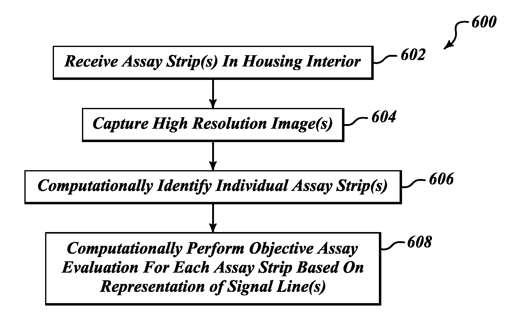
[0045]A method of operating an assay system to perform assays of assay strips may be summarized as including receiving a container enclosing a specimen along with number of assay strips in an interior of a housing; capturing at least one high resolution image of a portion of the interior of the housing in which the assay strips are received; computationally identifying individual ones of the assay strips in the captured high resolution image; and computationally performing the objective assay evaluation for each of the identified individual ones of the assay strips that appear in the captured high resolution image based at least in part on a representation of at least one signal line of each of the assay strips in the captured high resolution image. Capturing at least one high resolution image in the interior of the housing may include capturing at least one high resolution image of an area in the interior of the housing having a length and a width that is greater than a length and a wi

Problems solved by technology

Resulting test and control signal lines vary greatly in intensity, resulting in highly subjective user analysis.
The issue is further clouded by the nature of assay strips which sometimes contain a high level of background color, that may be incorrectly identified as a positive test line.
Thus, assay strips typically provide results which are at best semi-quantitative and are typically subject to variance by the person performing the assay.
Since quantification cannot be performed accurately with the naked eye and hence an exact amount of an analyte cannot be determined, application is restricted.

Method used


Image

  • Apparatus, method and article to perform assays using assay strips
  • Apparatus, method and article to perform assays using assay strips
  • Apparatus, method and article to perform assays using assay strips

Examples


Embodiment Construction

[0097]In the following description, certain specific details are set forth in order to provide a thorough understanding of various disclosed embodiments. However, one skilled in the relevant art will recognize that embodiments may be practiced without one or more of these specific details, or with other methods, components, materials, etc. In other instances, well-known structures associated with apparatuses, methods and articles for performing assays using lateral flow strips have not been shown or described in detail to avoid unnecessarily obscuring descriptions of the embodiments.

[0098]Unless the context requires otherwise, throughout the specification and claims which follow, the word “comprise” and variations thereof, such as, “comprises” and “comprising” are to be construed in an open, inclusive sense, that is as “including, but not limited to.”

[0099]Reference throughout this specification to “one embodiment” or “an embodiment” means that a particular feature, structure or cha...


PUM


Abstract

An assay system includes an optical imager to acquire high resolution images of assay strips (e.g., lateral flow immunochromatographic test strips) and performs image processing to identify individual assay strips and determine results for each assay strip, by quantifies the presence or absence of test signal line(s) and control signal line(s). Assay strips may be in a holder or carrier contained in a specimen container also holding a specimen. The assay system automatically logs all results and data to a database that stores a high resolution image of the original immunochromatographic assay, the values of test line(s) and control line(s), and the test result. A user interface directs an end user through operation.

Description

CROSS REFERENCE TO RELATED APPLICATIONS[0001]This application claims benefit under 35 U.S.C. 119(e) of U.S. Provisional Patent Application Ser. No. 61 / 189,931, filed Aug. 22, 2008 and entitled “APPARATUS, METHOD AND ARTICLE TO PERFORM ASSAYS USING ASSAY STRIPS,” which is incorporated herein by reference in its entirety.BACKGROUND[0002]1. Technical Field[0003]The present disclosure generally relates to the performance of assays using assay strips, for example chromatographic lateral flow strips.[0004]2. Description of the Related Art[0005]Performance of biological assays has been by greatly facilitated by the introduction of substrates for performing chromatographic assays. Since its conception, numerous substrates have been proposed for performing chromatographic assays. Such substrates are commonly referred to assay test strips or immunochromatographic strips. One type of assay strip is commonly referred to as chromatographic lateral flow strips or lateral flow strips. Other types ...

Claims


Application Information

Patent Timeline
IPC IPC(8): G06K9/00H04N7/18
CPCG01N21/8483G01N2035/00108G01N21/77G06F19/366G06F19/3406G16H40/63G16H10/40
Inventor FLEMING, JAMES E.MCGREW, JESSE M.MCGREW, STEPHEN P.NICHOLES, PATRICKHUMPHREYS, JOHNNY
Owner GENPRIME
Learn More