
Two-dimensional filter arithmetic device and method

a filter and arithmetic technology, applied in the field of two-dimensional filter arithmetic devices, can solve the problems of increasing the amount of calculation required, many standards flooding at the moment, and performing complicated compression/expansion processing

Inactive Publication Date: 2010-02-25
SOVEREIGN PEAK VENTURES LLC
View PDF5 Cites 10 Cited by
  • Summary
  • Abstract
  • Description
  • Claims
  • Application Information

AI Technical Summary

Benefits of technology

[0042]According to the present invention, it is possible to provide a two-dimensional filter arithmetic device which does not require a buffer for absorbing the difference of the filtering directions and allows an easy change of the sequence of the filtering directions, when performing two-dimensional filtering to the pixel values of pixels on a picture.

Problems solved by technology

In this way, many standards are flooding currently, based on different kinds of motion picture encoding technology.
On the other hand, the motion picture encoding technology in recent years is performing complicated compression / expansion processing for the improvement in compression ratio of a motion picture.
For this reason, if the number of pixels of the picture for compression / expansion processing increases, the required amount of calculation will become huge.
Since the software processing by such a CPU with a low operating frequency is not speedy enough to perform the expansion processing (decoding processing) of the motion picture which requires the huge amount of calculation as mentioned above, the video equipment often mounts a hardware dedicated for the expansion processing to practice processing algorithm directly.
The dedicated hardware is not easy to change its functions after mounting.
The path of the control circuit for controlling the buffer is required separately, in addition to the data path which practices the filter arithmetic, thereby causing increase in the circuit area.
This problem is surely encountered, when the data path which practices the vertical direction filtering and the data path which practices the horizontal direction filtering possess the same data path structure as those in the conventional art.
In the conventional two-dimensional filter illustrated in FIG. 16, there is another problem in that sequence of the filtering direction can not be changed easily.

Method used


Image

  • Two-dimensional filter arithmetic device and method
  • Two-dimensional filter arithmetic device and method
  • Two-dimensional filter arithmetic device and method

Examples


embodiment 1

[0060]Embodiment 1 of the present invention treats the two-dimensional filtering in the motion compensated prediction arithmetic which is in conformity with H.264|MPEG-4 AVC as an example.

[0061]The present invention can be applied to general two-dimensional filter arithmetic, and is not limited to the present embodiment.

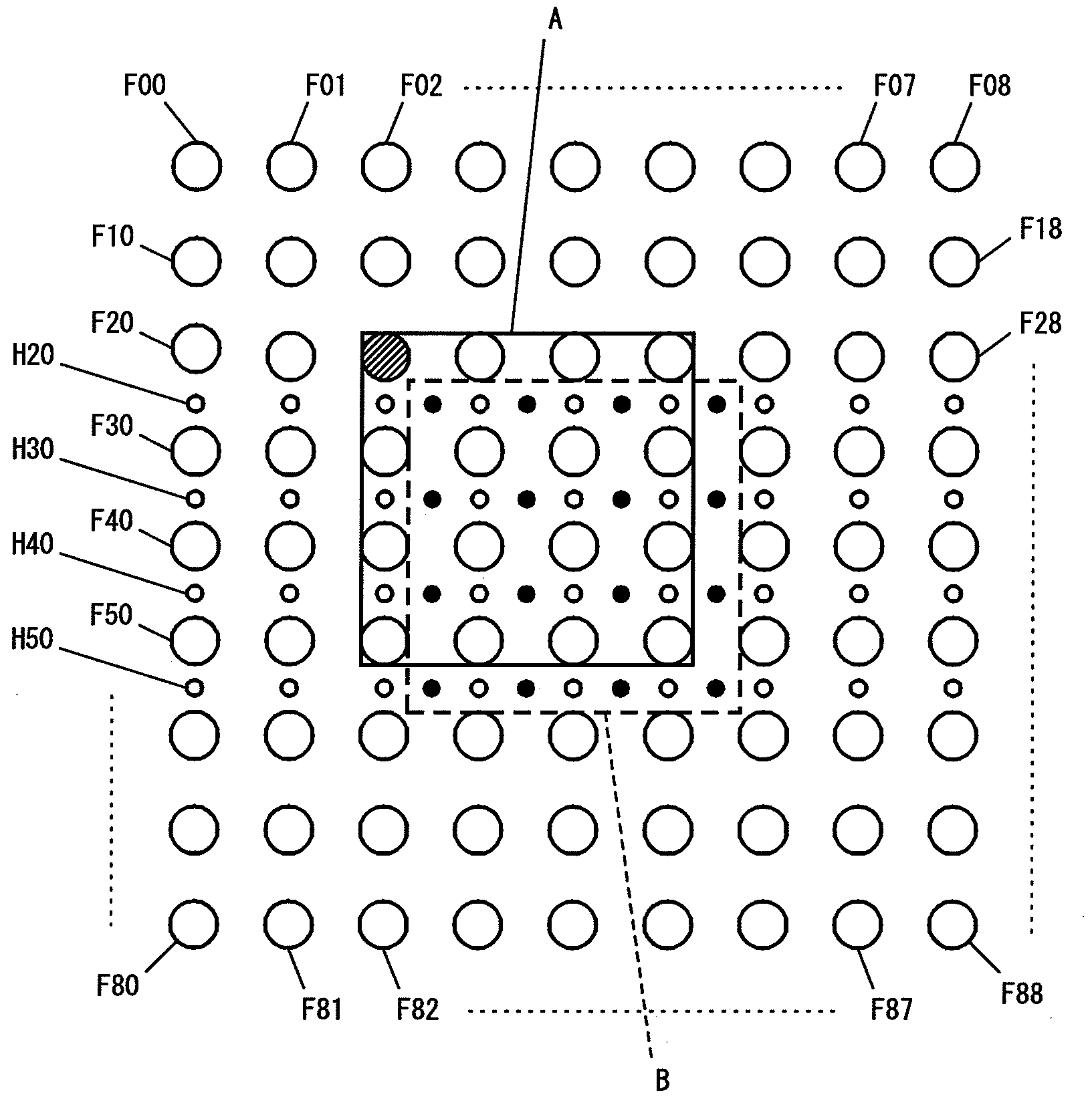
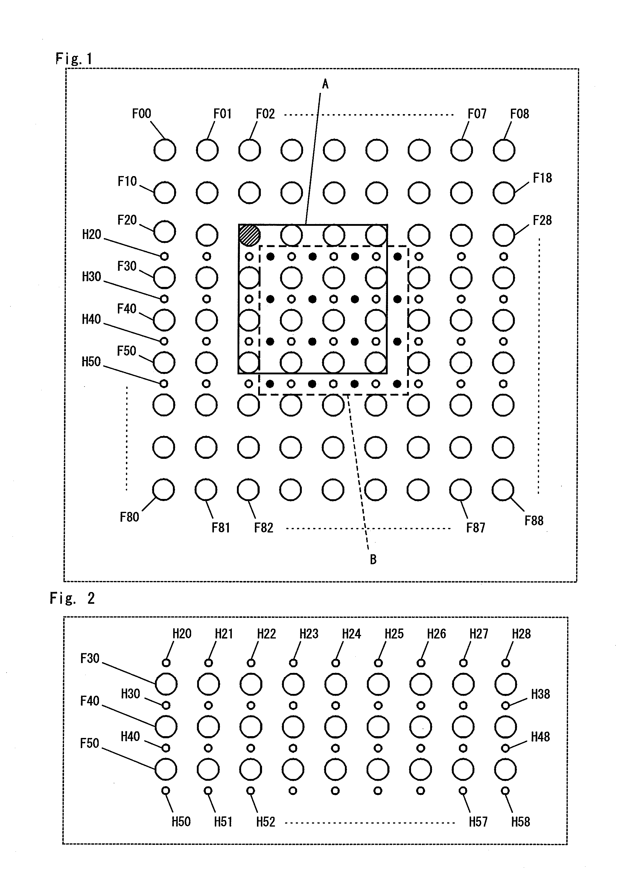
[0062]In the motion compensated prediction arithmetic illustrated by the present embodiment, it is assumed that a picture area composed of the (4×4) pixels of full-pel precision is translated to a new picture area according to a motion vector (½, ½), and that the pixel values of pixels of half-pel precision included in the new picture area are calculated. In the present arithmetic, the pixel value of the pixel of half-pel precision included in the new picture area is calculated by performing the two-dimensional filter arithmetic with 6 taps to the pixel values of the pixels of full-pel precision. (In the following description, a pixel of full-pel precision is called ...

embodiment 2

[0159]FIG. 10 is a block diagram illustrating a two-dimensional filter arithmetic device in Embodiment 2 of the present invention. The two-dimensional filter arithmetic device according to the present embodiment comprises a picture memory 300, a line memory 400, a vertical filtering unit 640, a horizontal filtering unit 650, a first selector 610, a second selector 620, and a third selector 630.

[0160]The two-dimensional filter arithmetic device of the present embodiment possesses two operation modes. Namely, in the case of the first operation mode, the vertical direction filter arithmetic is practiced first, and the horizontal direction filter arithmetic is practiced next. In the case of the second operation mode, the horizontal direction filter arithmetic is practiced first, and the vertical direction filter arithmetic is practiced next. Namely, the two-dimensional filter arithmetic device of the present embodiment can change arbitrarily the sequence of the vertical direction filter...

embodiment 3

[0189]FIG. 13 is a block diagram illustrating a semiconductor integrated circuit in Embodiment 3 of the present invention. The semiconductor integrated circuit 700 according to the present embodiment comprises a two-dimensional filter arithmetic unit 710, CPU 720, an encoding / decoding unit 730, a memory 740, and a functional circuit unit 750. The two-dimensional filter arithmetic unit 710 includes a vertical filtering unit 711 and a horizontal filtering unit 712.

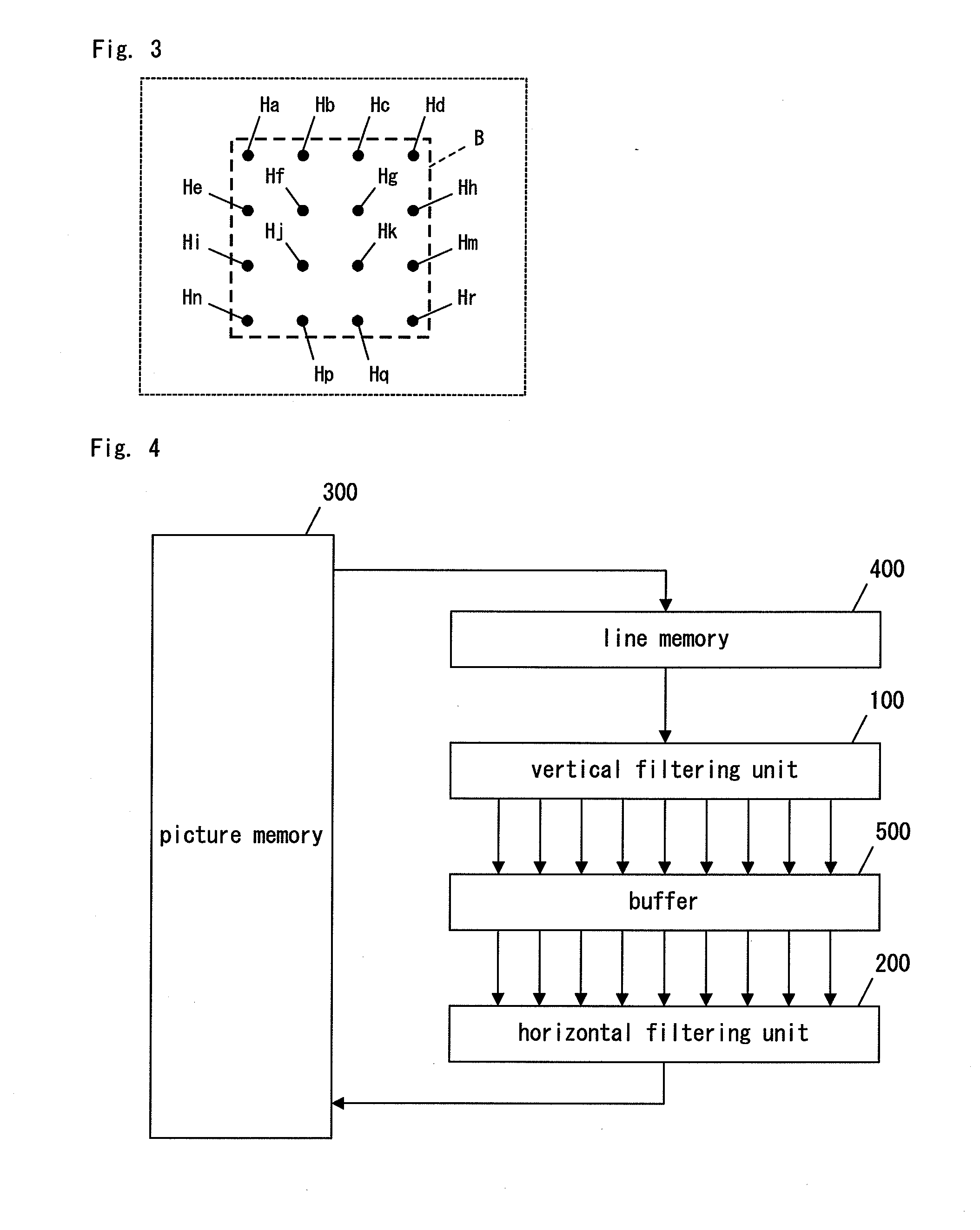
[0190]The two-dimensional filter arithmetic unit 710 of the present embodiment corresponds to the two-dimensional filter arithmetic device which is illustrated in FIG. 4 and was explained in Embodiment 1 of the present invention. Namely, the vertical filtering unit 711 of the present embodiment includes the vertical filtering unit 100 and the line memory 400, shown in FIG. 4. The horizontal filtering unit 712 of the present embodiment includes the horizontal filtering unit 200 and the buffer 500, shown in FIG. 4.

[0191]To pic...


PUM


Abstract

A two-dimensional filter arithmetic device comprises a picture memory (300), a line memory (400), a vertical filtering unit (100) which includes nine first filter modules installed in parallel, a buffer (500) for timing adjustments, and a horizontal filtering unit (200) which includes four second filter modules installed in parallel. From the line memory (400), the pixel values of nine full pels per line are inputted in parallel to the vertical filtering unit (100), nine vertically-filtered values of half pels are generated and inputted to the horizontal filtering unit (200); thereby, four two-dimensionally-filtered values of half pels are generated.

Description

TECHNICAL FIELD [0001]The present invention relates to a two-dimensional filter arithmetic device to be used for picture compression / expansion processing, in-loop filter processing, scanning line conversion processing, or picture smoothing processing.BACKGROUND ART [0002]In recent years, the voice encoding technology and motion picture encoding technology based on compression technology of voice and picture data are very important technology in enriching our audio visual life.[0003]Various systems are proposed for the motion picture encoding technology nowadays. As the standards of the motion picture encoding technology, H.261 and H.263 are proposed by ITU-T (International Telecommunication Union-Telecommunication Standardization Sector), and MPEG-1, MPEG-2, and MPEG-4 are proposed by ISO (International Organization for Standardization). (MPEG is the abbreviation of Moving Picture Experts Group). Recently, H.264|MPEG-4 AVC (Advanced Video Coding) has been standardized by ITU-T and I...

Claims


Application Information

Patent Timeline
IPC IPC(8): G06K9/40H04N9/79
CPCG06T3/4007H04N19/82G06T2200/28
Inventor INOUE, AKIHIKOKIYOHARA, TOKUZO
Owner SOVEREIGN PEAK VENTURES LLC
Learn More