WDM PON RF overlay architecture based on quantum dot multi-wavelength laser source

a quantum dot and laser source technology, applied in the field of wavelength division multiplexed passive optical networks, can solve problems such as limitations of wdm-pons

Active Publication Date: 2010-02-25
LG ERICSSON
View PDF6 Cites 22 Cited by
  • Summary
  • Abstract
  • Description
  • Claims
  • Application Information

AI Technical Summary

Problems solved by technology

WDM-PONs suffer a limitation in that they are d

Method used


Image

  • WDM PON RF overlay architecture based on quantum dot multi-wavelength laser source
  • WDM PON RF overlay architecture based on quantum dot multi-wavelength laser source
  • WDM PON RF overlay architecture based on quantum dot multi-wavelength laser source

Examples


Embodiment Construction

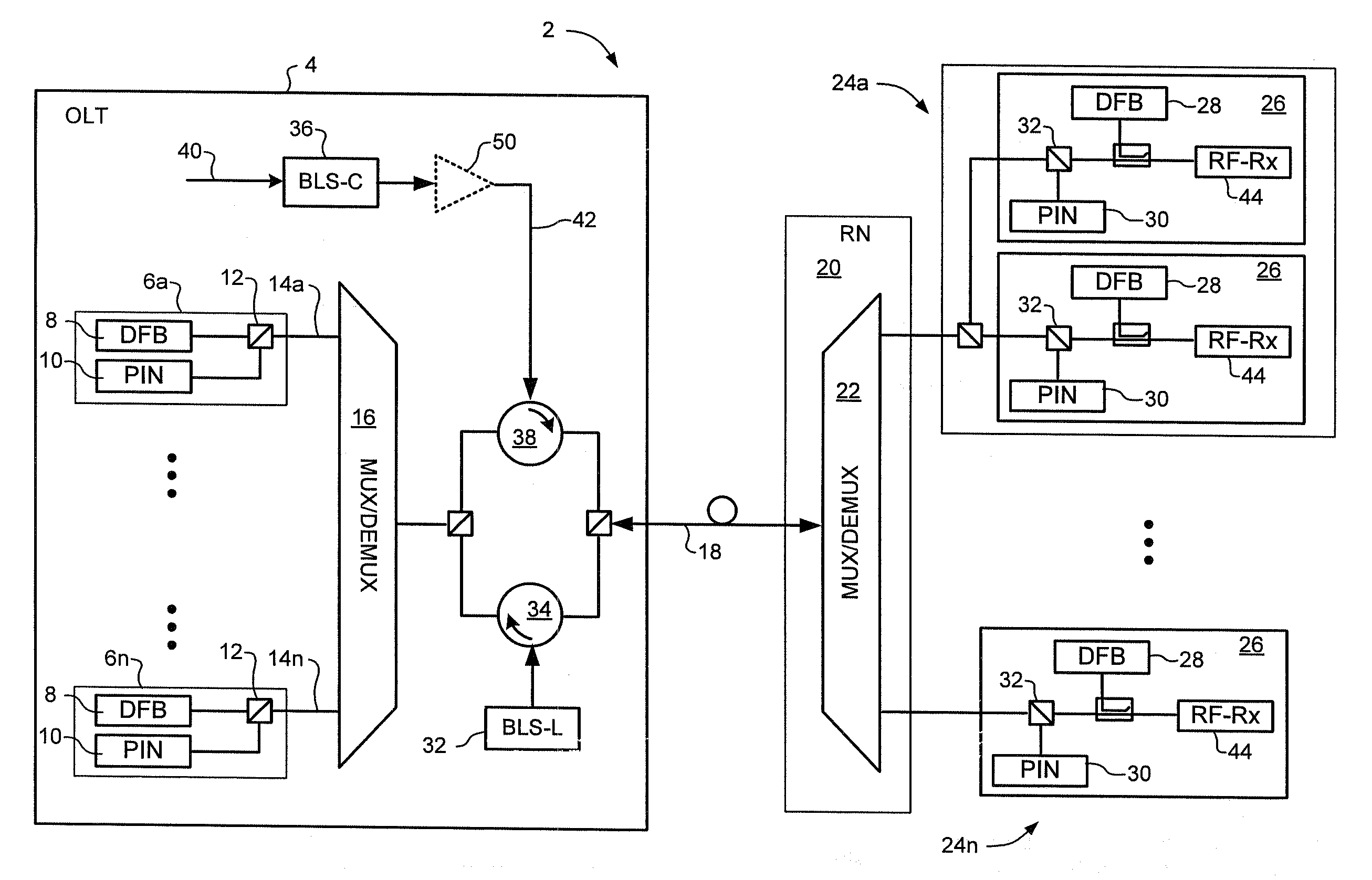
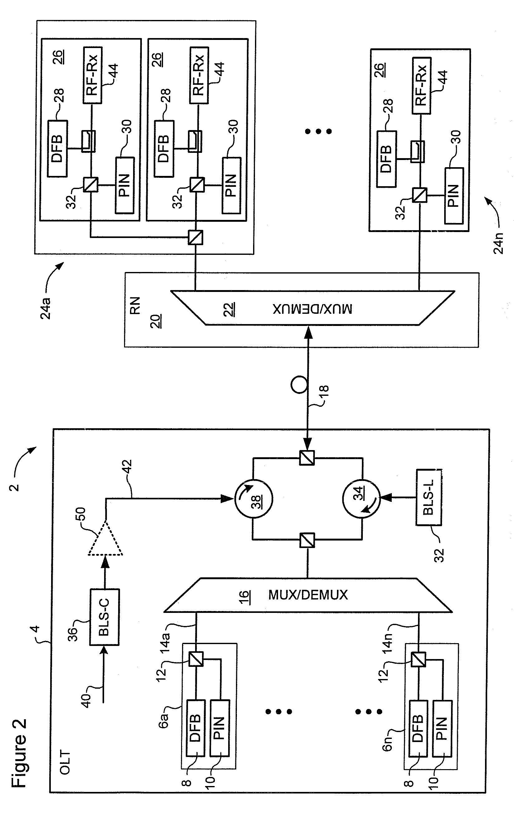
[0017]The present invention provides techniques for overlaying RF-Video broadcast signalling on a Wavelength Division Multiplexing Passive Optical Network (WDM-PON). A representative embodiment is described below with reference to FIGS. 2-4.

[0018]Referring to FIGS. 2-4, in very general terms, analog RF / Video signals 40 are modulated onto the uplink seed light 42 which is distributed to the ONT(s) 26 at each customer site. At each ONT 26, the inbound seed light is divided into two signals; one of which is used as a seed light for the light source 28, and the other is supplied to an RF receiver 44 for detection of the RF / Video signals.

[0019]If desired, the uplink seed light 42 can be generated by a broadband light source (BLS) 36 in a conventional a manner. FIGS. 3a and 3b illustrate representative embodiments of the BLS 36, in which a set of narrow-band lasers 46 are used to generate respective narrow band seed lights, each of which is tuned to the center wavelength of a respective u...


PUM


Abstract

In a Wavelength Division Multiplexed Passive Optical Network (WDM-PON) including, a system for overlaying an analog broadcast signal. An Optical Line Terminal of the WDM-PON includes a broadband light source for generating uplink seed light for each uplink channel of the WDM-PON, and a modulator for modulating the analog broadcast signal onto the uplink seed light. An Optical Network Terminal of the WDM-PON receives the uplink seed light from the Optical Line Terminal, and includes an optical divider for dividing the received seed light into a first signal and a second signal; a light source for generating an uplink data signals using the first signal as seed light; and an RF receiver for detecting the analog broadcast signal modulated on the second signal.

Description

CROSS-REFERENCE TO RELATED APPLICATIONS[0001]This application is based on, and claims priority from, U.S. Provisional Patent Application Ser. No. 61 / 090,644, filed Aug. 21, 2008, the entire contents of which are incorporated herein by reference.FIELD OF THE INVENTION[0002]The present application relates generally to Wavelength Division Multiplexed Passive Optical Networks (WDM PON) and, more specifically, to a method to overlay analog RF / Video broadcast signalling on a WDM-PON network.BACKGROUND OF THE INVENTION[0003]A passive optical network (PON) is a point-to-multipoint network architecture in which unpowered optical splitters are used to enable a single optical fibre to serve multiple premises. A PON typically includes an Optical Line Terminal (OLT) at the service provider's central office connected to a number (typically 32-128) of Optical Network Terminals (ONTs), each of which provides an interface to customer equipment.[0004]In operation, downstream signals are broadcast fro...

Claims


Application Information

Patent Timeline
IPC IPC(8): H04J14/02H04B10/2581
CPCH04J14/0226H04J14/0282H04J14/02H04J14/0265H04J2014/0253H04J14/0298H04J14/0232H04J14/0246H04J14/025H04J14/0267H04B10/2581
Inventor CAO, BINCHEN, RONG
Owner LG ERICSSON
Why Eureka
Try Eureka