

Quantum communication apparatus, quantum communication system and quantum communication method
a communication apparatus and quantum communication technology, applied in the field of quantum encryption communication apparatus, can solve the problem that security cannot be assured over a communication distance of about 25 km (kilometers), and achieve the effect of stable and highly efficient quantum communication
- Summary
- Abstract
- Description
- Claims
- Application Information
AI Technical Summary
Benefits of technology
Problems solved by technology
Method used
Image

Examples
first embodiment
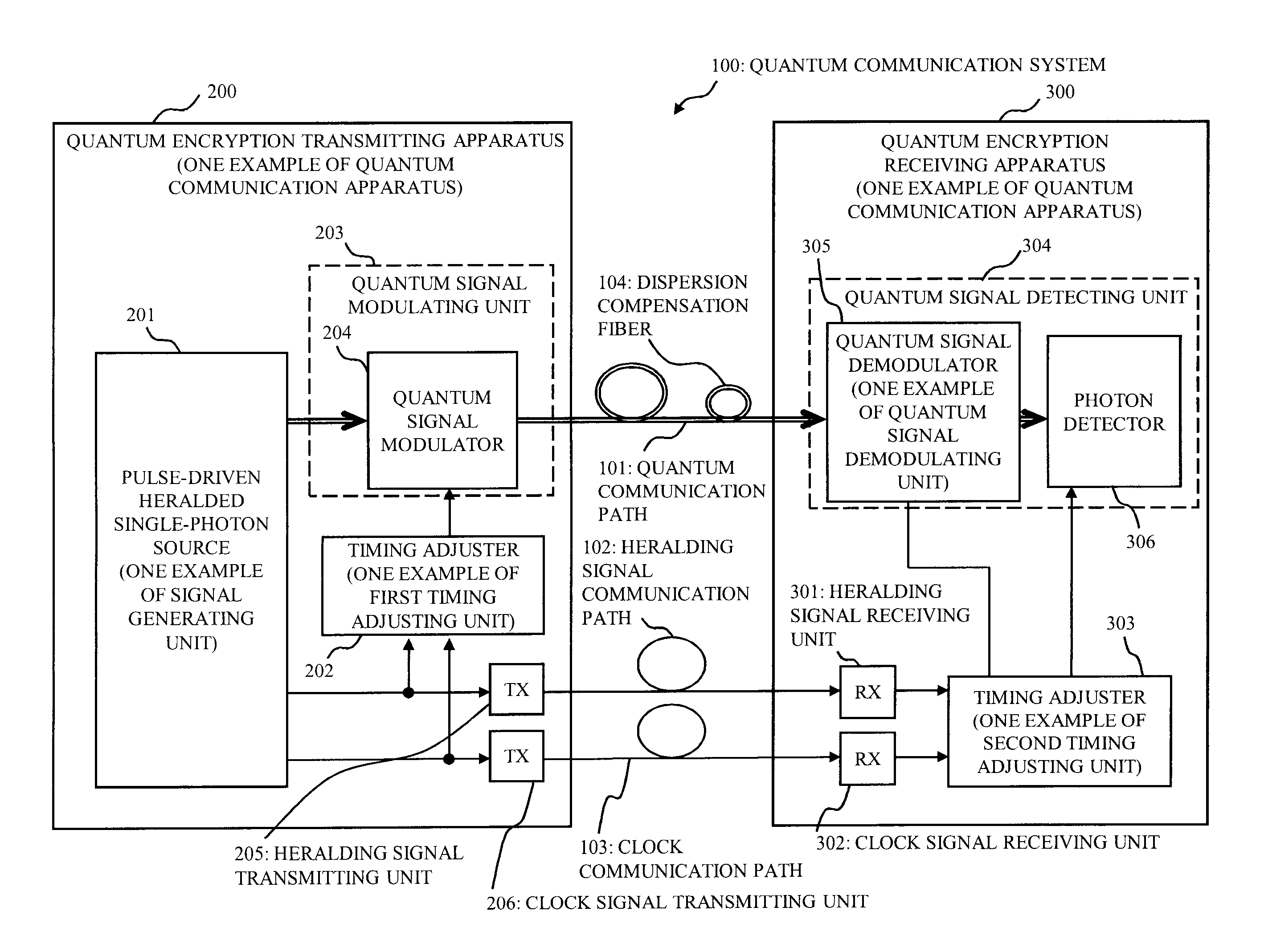
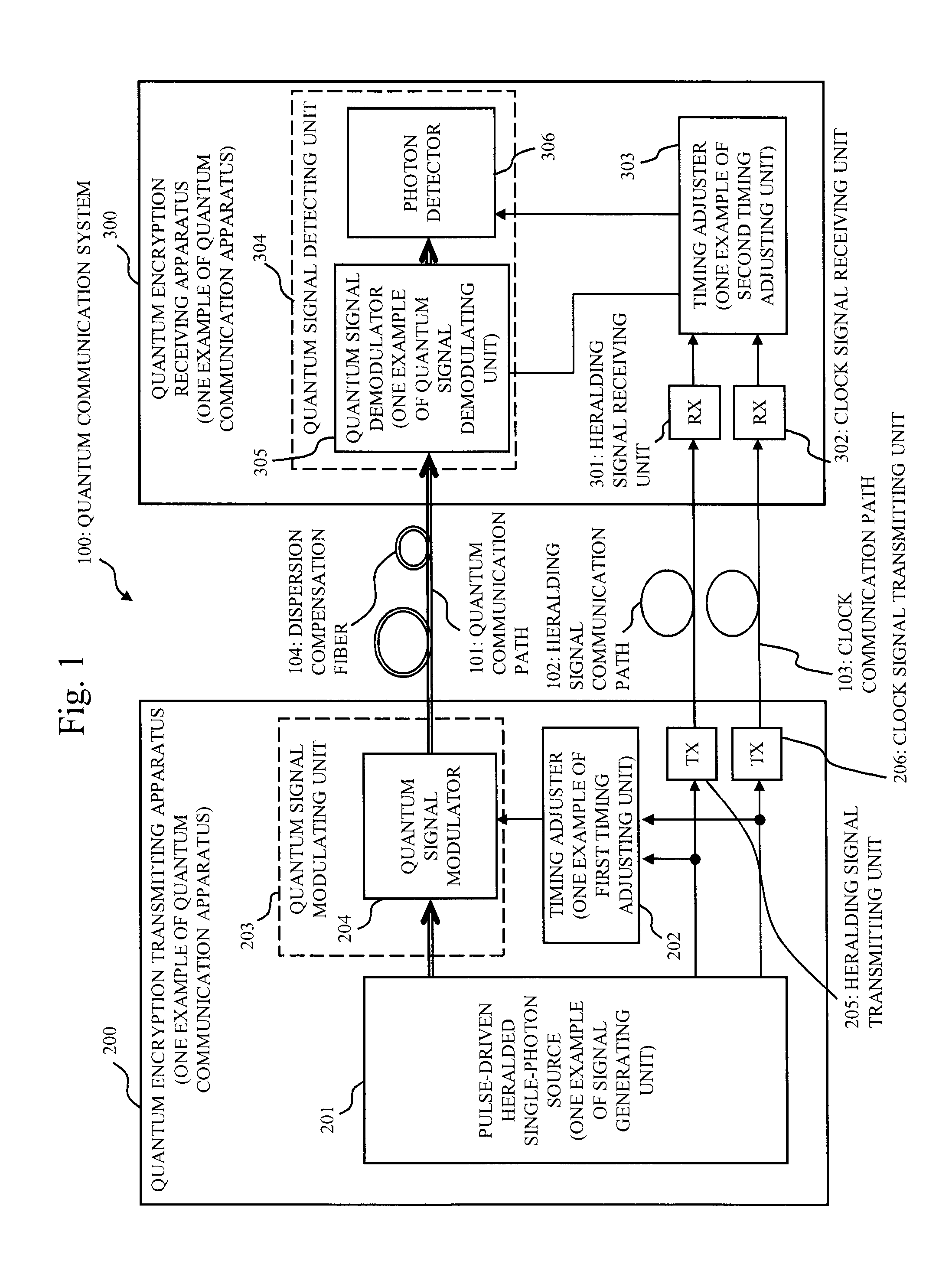
[0064]FIG. 1 is a block diagram showing a configuration of a quantum communication system 100 of the present embodiment.
[0065]Referring to FIG. 1, the quantum communication system 100 (also referred to as “quantum encryption communication system”) includes a quantum encryption transmitting apparatus 200, a quantum encryption receiving apparatus 300, a quantum communication path 101 (also referred to as “quantum signal communication path”), a heralding signal communication path 102, and a clock communication path 103 (also referred to as “pulse clock communication path” or “pulse clock signal communication path”) that connect the two apparatuses.
[0066]The quantum communication path 101 is a communication path that conveys a photon as a quantum signal. For a case in which the quantum communication path 101 uses an optical fiber to communicate in long distance, a dispersion compensation fiber 104 may be connected subsequently to it in order to compensate a collapse in an optical pulse ...
second embodiment
[0102]The present embodiment, mainly differences from the first embodiment, will be described.
[0103]The first embodiment employs the configuration in which the pulse laser serving as the pump light source of the pulse-driven heralded single-photon source 201 is used as a master clock. In the present embodiment, a clock is shared at a low jitter in between the two quantum encryption communication apparatuses, and the pulse laser serving as the pump light source is synchronized and driven by using the shared clock as a master.
[0104]According to the first embodiment, in the quantum communication system 100, the clock signal that synchronizes the heralding signal for generating the trigger signal is transmitted from the quantum encryption transmitting apparatus 200 to the quantum encryption receiving apparatus 300. However, in the present embodiment, it is transmitted from the quantum encryption receiving apparatus 300 to the quantum encryption transmitting apparatus 200.
[0105]FIG. 7 is...
third embodiment
[0114]The present embodiment, mainly differences from the first embodiment, will be described.
[0115]The first embodiment employs the configuration in which, in the quantum signal detecting unit 304 of the quantum encryption receiving apparatus 300, the quantum signal demodulator 305 is used, and the measurement means of the quantum state of the photon transmitted from the quantum encryption transmitting apparatus 200 is selected actively. The present embodiment employs a configuration in which, instead of using the quantum signal demodulator 305, the photon detectors 306 used for the measurement are increased, and the measurement means of the quantum state is selected passively.
[0116]FIG. 10 is a block diagram showing a configuration of the quantum communication system 100 of the present embodiment.
[0117]The main difference from FIG. 1 described in the first embodiment resides in that the quantum signal detecting unit 304 of the quantum encryption receiving apparatus 300 includes a ...
PUM
 Abstract
Description
Claims
Application Information