Oil sampling device having a flexible piston and chamber

a flexible piston and oil sampling technology, applied in the direction of piston pumps, laboratory glassware, instruments, etc., can solve the problems of difficult access, difficult to reach, and difficult to extract the oil sample, etc., to achieve the effect of compact storage size and sustained operation

Inactive Publication Date: 2010-03-04
SHELL OIL CO
View PDF6 Cites 6 Cited by
  • Summary
  • Abstract
  • Description
  • Claims
  • Application Information

AI Technical Summary

Benefits of technology

[0010]Any engines use lubricant oil to maintain their sustained operation for long time. The engines can be powered by gasoline, diesel, electric current, hydraulic, pneumatic or stream. In addition to motor oil, the present device also can be used to extract fluid samples from other places that are relatively difficult to access. The compact storage size of the present invention is another advantage over previous devices.

Problems solved by technology

The lubricating ability of these oils degrades as the engine is operated over time.
Because the oil pan is beneath the engine block, however, it is not readily accessed.
These devices rely on gravity flow, but require access to the underside of the engine, which is relatively difficult.
Because they cannot rely on gravity flow, however, these devices require means for drawing the oil up out of the oil reservoir.
This means that, depending on the required sample size, the distance through which the plunger must be withdrawn can be relatively great.
Because of shortcomings with the afore-mentioned device, the available technology for obtaining an oil sample remains less than satisfactory.
In some devices, such a those that use spring-loaded suction for withdrawing oil from the oil plan, the oil discharge mechanism may leave some oil clinging to the inside of the sample tube.
This can contaminate the subsequent sample, resulting in a false reading or analysis.
In addition, the combined length of the plunger, handle, and sample tube can be well over four feet, making the device difficult to handle.
Still further, the plunger, when it has been retracted, is susceptible to buckling when force is applied to return it to its starting position.

Method used


Image

  • Oil sampling device having a flexible piston and chamber
  • Oil sampling device having a flexible piston and chamber
  • Oil sampling device having a flexible piston and chamber

Examples


Embodiment Construction

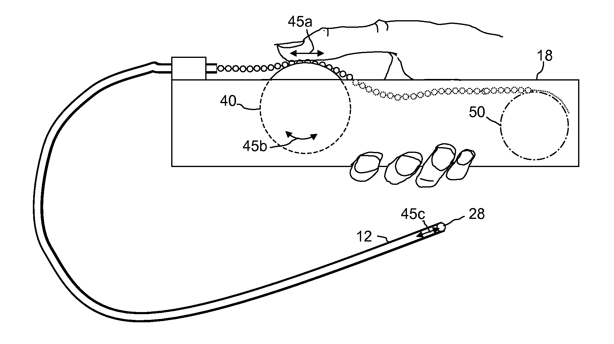
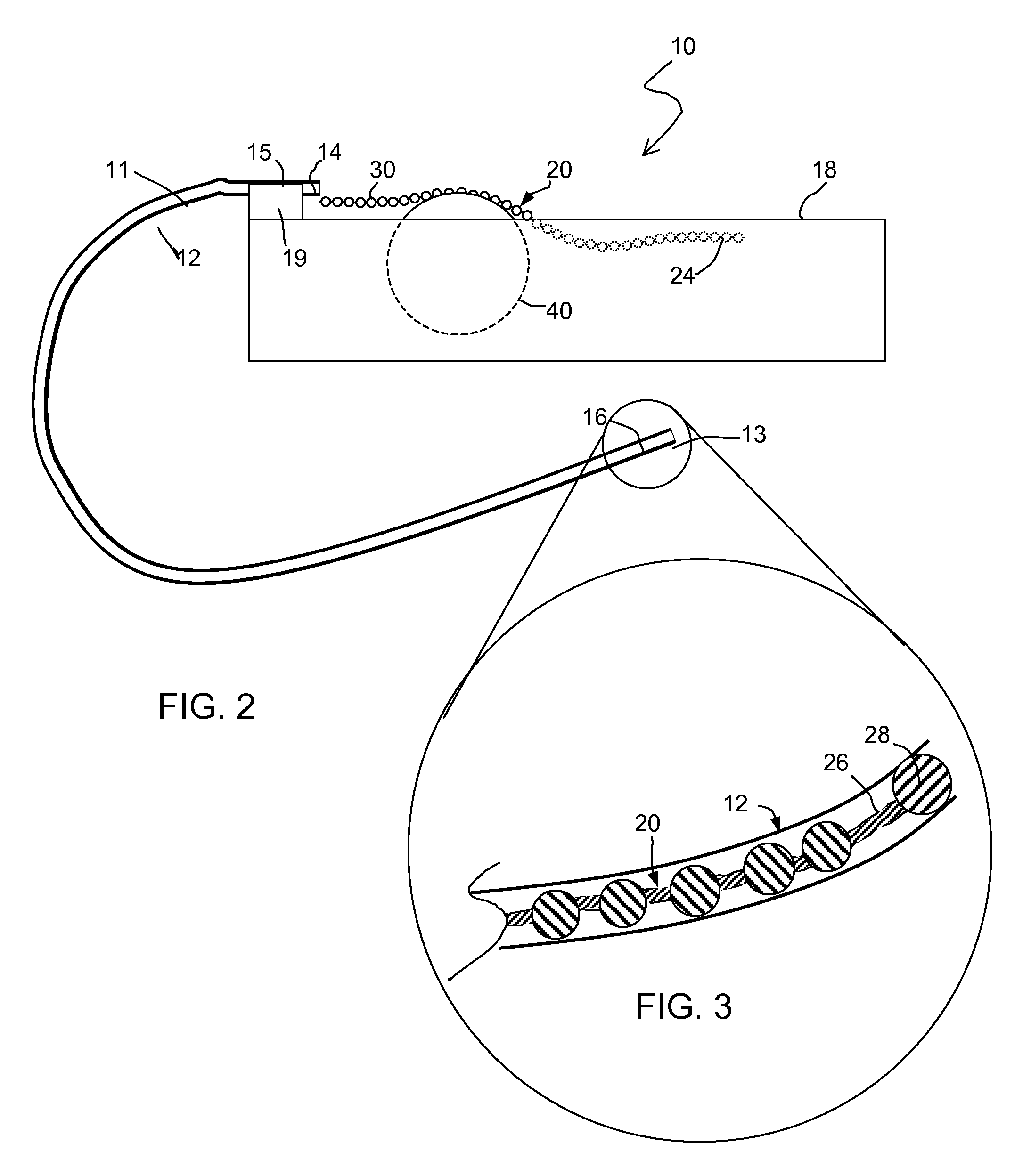
[0019]Referring now to FIGS. 2 and 3, an oil extractor 10 constructed in accordance with a first embodiment of the invention includes a chamber 12 having a proximal end 14 and a distal end 16, a handle 18 affixed to the proximal end of chamber 12, and a piston member 20 slidably disposed within chamber 12. Chamber 12 includes an oil inlet 13. In certain embodiments, chamber 12 comprises a length of flexible tubing 11, and in particular embodiments may be constructed of a flexible, heat-resistant, transparent or translucent plastic.

[0020]Chamber 12 may be attached to handle 18 by any suitable means, such as a mounting clip 15. Mounting clip 15 may comprise a body 19 having a bore 17 (FIG. 4) therethrough. Proximal end 14 of chamber 12 may be disposed in bore 17 and affixed thereto, such as by adhesive or other means. Alternatively, proximal end 14 may be affixed to the outside of body 19, or directly to handle 18, if desired.

[0021]Piston member 20 is slidably disposed in chamber 12. ...


PUM


Abstract

A device, system, and method for retrieving a sample of oil from an engine, comprising, a chamber having an inside wall and at least one oil inlet, a piston head received in said chamber and slidable between an empty position in which it is disposed substantially at said inlet and a filled position in which it is a first distance from said inlet, a handle affixed to said chamber, and a piston member extending between said handle and said piston head, said piston member comprising a flexible member having a proximal end and a distal end, said distal end being affixed to said piston head.

Description

FIELD OF INVENTION[0001]The invention generally relates to a device and method for extracting a fluid sample from a reservoir that is relatively difficult to reach. More particularly, the present invention relates to a device and method for extracting a sample of motor oil from an engine.BACKGROUND OF THE INVENTION[0002]It is well known in the motor vehicle arts that the rate of mechanical wear on the engine depends in part on the lubricating ability of the oil that is used to lubricate the engine parts, (sometimes referred to as “engine oil” or “motor oil”). The lubricating ability of these oils degrades as the engine is operated over time. In order to prevent catastrophic failures, there are various tests and guidelines for determining when an engine oil should be changed. Because of the range of conditions under which an engine may be operated, however, it is more reliable to test the oil in question than to rely solely on guidelines to determine when an oil should be changed.[00...

Claims


Application Information

Patent Timeline
Patent Type & Authority Applications(United States)
IPC IPC(8): F04B9/14
CPCB01L3/0217B01L2300/123G01N2001/1427G01N1/14F01M11/045Y10T137/86099
Inventor SHAH, VATSAL MUKUNDLALWANG, PRIESTLEY JINH-KONG
Owner SHELL OIL CO
Why Eureka
Try Eureka