
Monolithic Dual Band Imager

a dual-band, imager technology, applied in the field of imaging sensors, can solve the problems of inconvenient use, inconvenient use, and inability to identify objects, and achieve the effects of reducing the number of mwir imagers

Inactive Publication Date: 2010-03-04
PRINCETON LIGHTWAVE INC
View PDF2 Cites 40 Cited by
  • Summary
  • Abstract
  • Description
  • Claims
  • Application Information

AI Technical Summary

Benefits of technology

[0015]An embodiment of the present invention comprises: an imaging sensor comprising; a substrate; and an array of pixels, wherein the pixels and substrate are monolithically integrated, and wherein each pixel comprises; a first photodiode, wherein the first photodiode is photoresponsive for light that is characterized by a wavelength within a first range and non-photoresponsive for

Problems solved by technology

MWIR imagers are not well-suited to the identification of an object, however, as they are not capable of detecting such things as facial features or markings on clothing.
Unfortunately, such systems are bulky, expensive, and power inefficient.
Their use in practical systems, therefore, has been limited—particularly where portability is desired.
Unfortunately, such photodiodes are well-known to exhibit large dark currents (i.e., noise).
As a result, these imagers tend to be expensive, bulky, and extremely power inefficient.

Method used


Image

  • Monolithic Dual Band Imager
  • Monolithic Dual Band Imager
  • Monolithic Dual Band Imager

Examples


Embodiment Construction

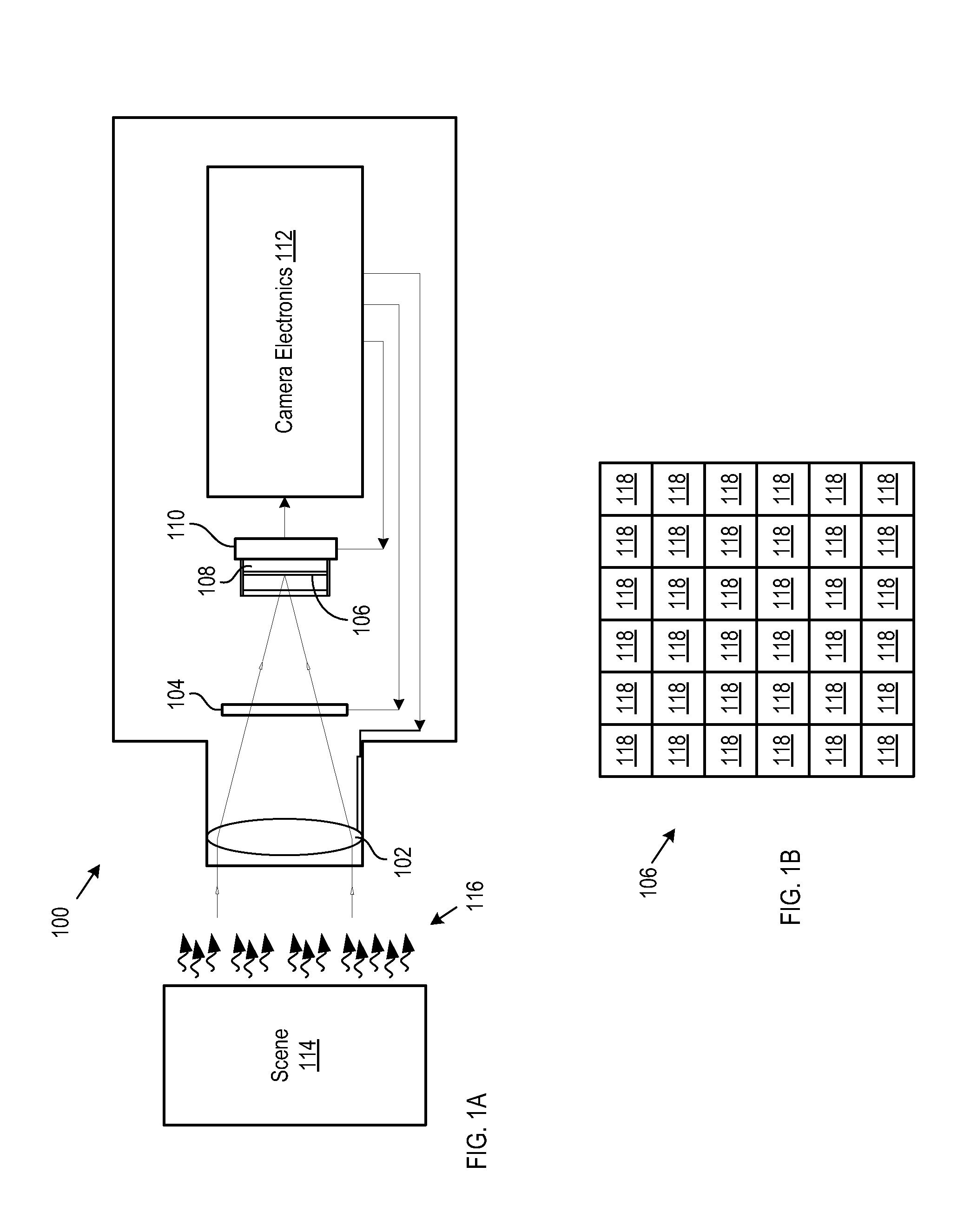
[0024]FIG. 1A depicts a schematic drawing of an infrared camera in accordance with an illustrative embodiment of the present invention. IR camera 100 comprises IR imaging optics 102, shutter 104, sensor array 106, read-out integrated circuit 108, temperature stabilizer 110, and camera electronics 112, interrelated as shown.

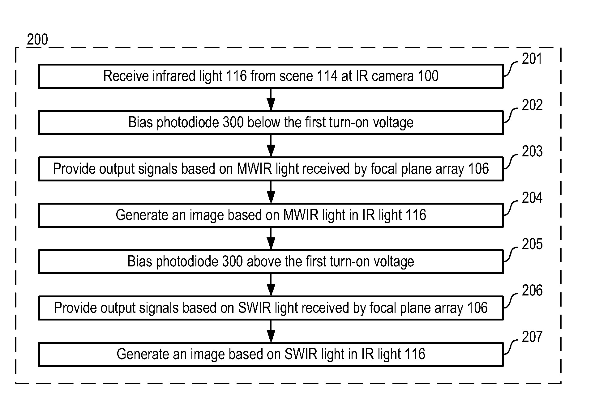
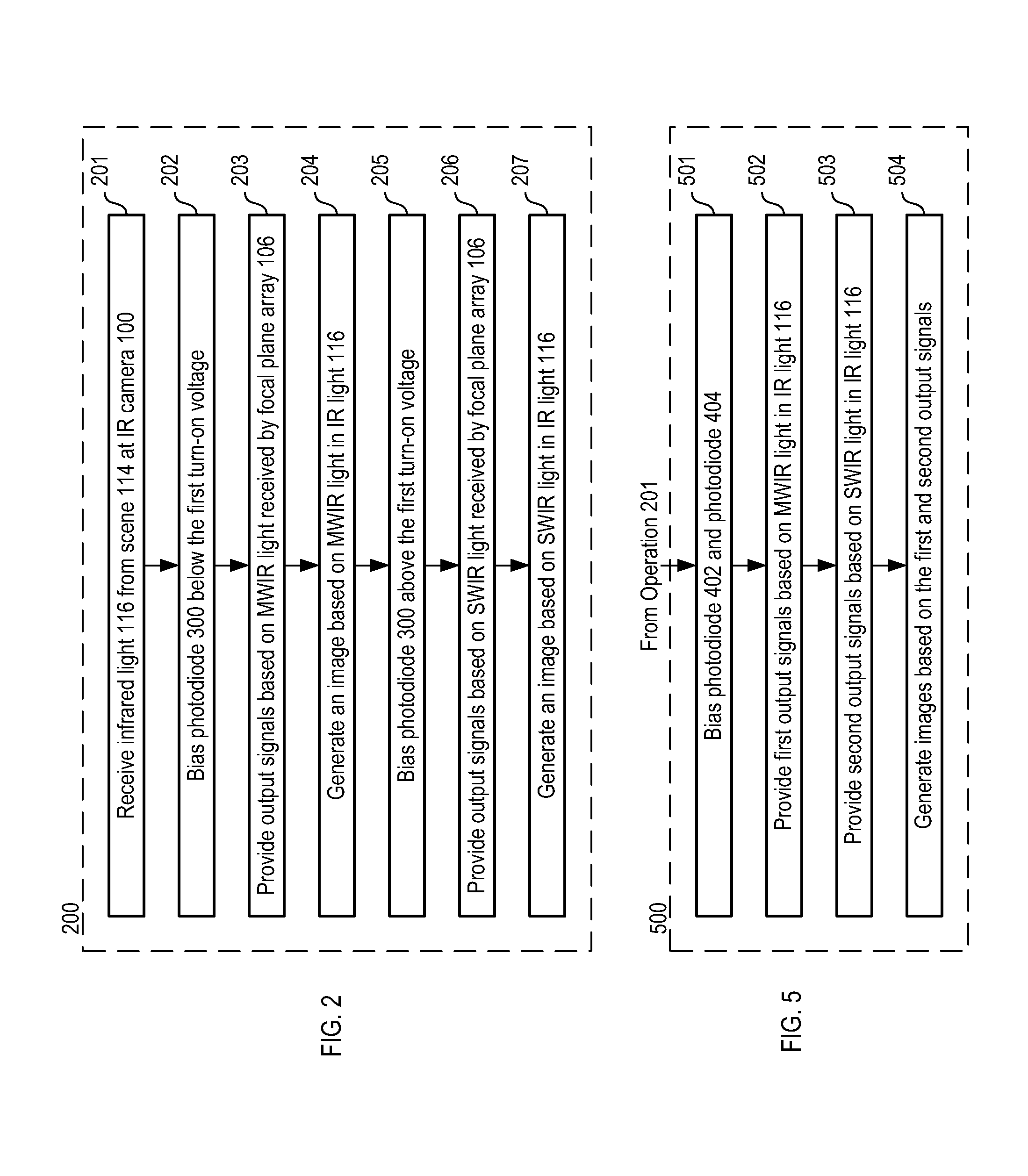
[0025]FIG. 2 depicts operations of a method for providing an image of a scene in accordance with the illustrative embodiment of the present invention. Method 200 is described herein with reference to FIGS. 3A-C and continuing reference to FIGS. 1A-B. Method 200 begins with operation 201, wherein IR light from scene 114 is received at IR camera 100.

[0026]IR imaging optics 102 include one or more lenses that receive radiant energy, such as infrared radiation. IR radiation that is received by IR imaging optics 102 is directed toward shutter 104. The shutter controls the amount of radiation that is directed toward sensor array 106. One skilled in the art will know how...


PUM


Abstract

An imaging sensor for imaging scenes based on both shortwave infrared and midwave infrared radiation is disclosed. The imaging sensor comprises pixels that include a photodiode that is selectively sensitive to shortwave infrared radiation based upon its bias voltage.

Description

CROSS REFERENCE TO RELATED APPLICATIONS[0001]This case claims priority of U.S. Provisional Patent Application U.S. 61 / 093,593, which was filed on Sep. 2, 2008 (Attorney Docket: 293-018US), and which is incorporated herein by reference.FIELD OF THE INVENTION[0002]The present invention relates to imaging sensors in general, and, more particularly, to infrared imaging sensors.BACKGROUND OF THE INVENTION[0003]Imaging sensors that are sensitive to infrared light are useful in many applications, such as automotive, fire fighting, security, and military applications. Infrared radiation (IR) includes several ranges of wavelengths; shortwave infrared (SWIR), which includes wavelengths from approximately 900 nanometers (nm) to approximately 3000 nm; midwave infrared (MWIR), which includes wavelengths from approximately 3000 nm to approximately 5000 nm; and longwave infrared (LWIR), which includes wavelengths longer than approximately 5000 nm. In many cases, the wavelength range of the imaging...

Claims


Application Information

Patent Timeline
IPC IPC(8): H01L31/09H01L31/0352
CPCB82Y20/00H01L27/14652H01L31/1075H01L31/1035H01L31/035236
Inventor ONAT, BORA MUAMMERITZLER, MARK ALLEN
Owner PRINCETON LIGHTWAVE INC
Learn More