Eureka AIR delivers breakthrough ideas for toughest innovation challenges, trusted by R&D personnel around the world.

Sealing device

a sealing device and sealing technology, applied in the direction of mechanical equipment, machines/engines, transportation and packaging, etc., can solve the problems of wear and tear of the sliding contact seal lip, and achieve the effects of reducing the friction resistance of the sliding contact treated surface, reducing the rotary torque, and reducing the heat generation temperature of the sealing lip

Active Publication Date: 2010-03-04
UCHIYAMA MFG
View PDF4 Cites 27 Cited by
  • Summary
  • Abstract
  • Description
  • Claims
  • Application Information

AI Technical Summary

Benefits of technology

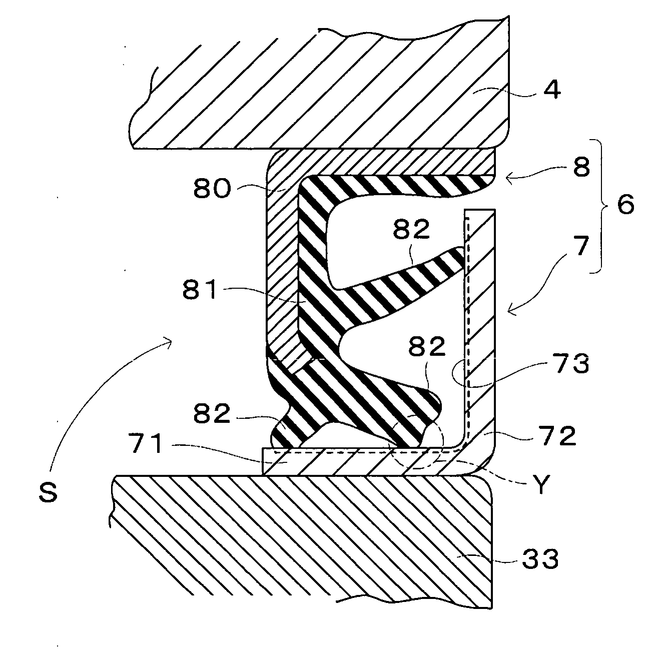
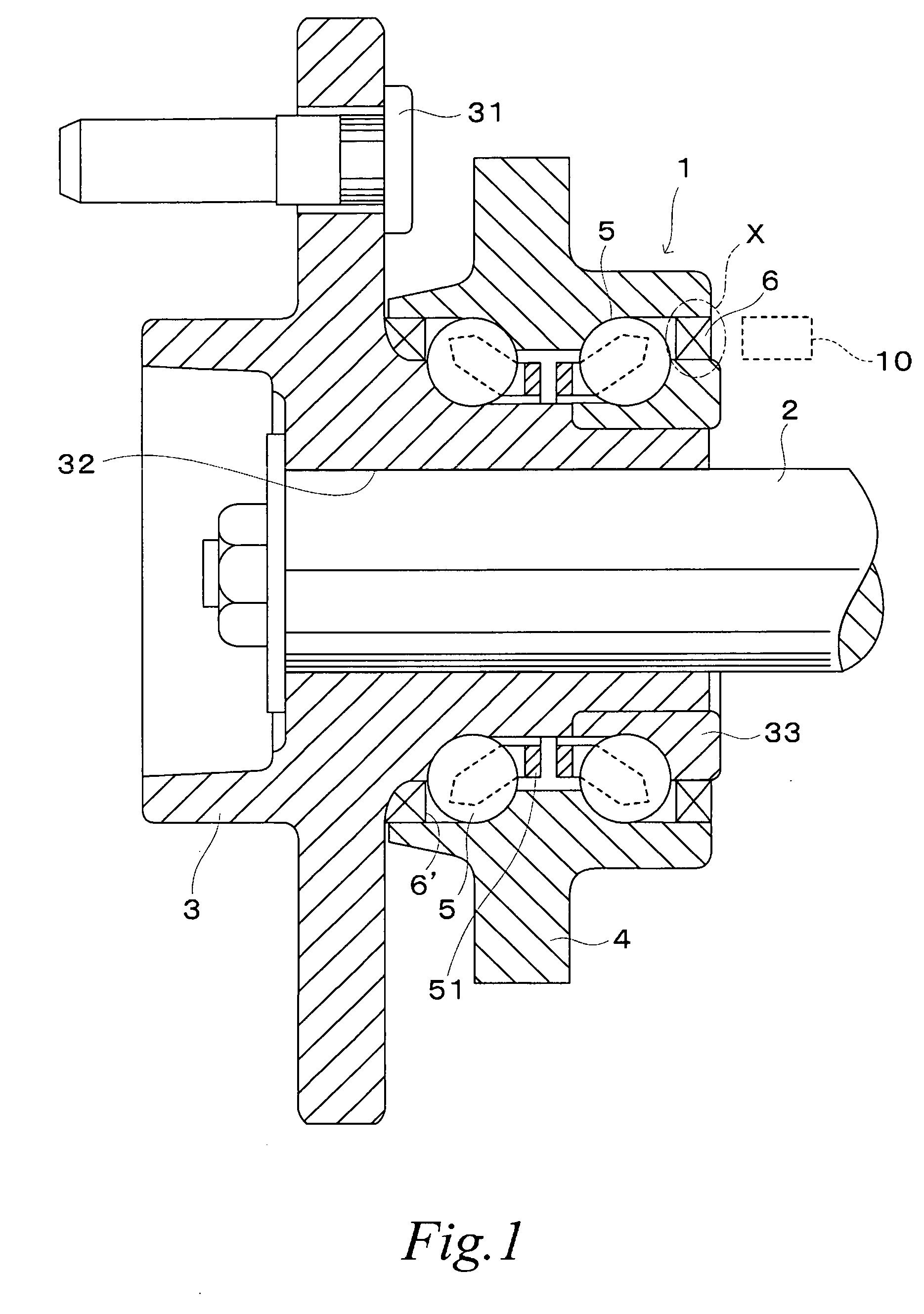
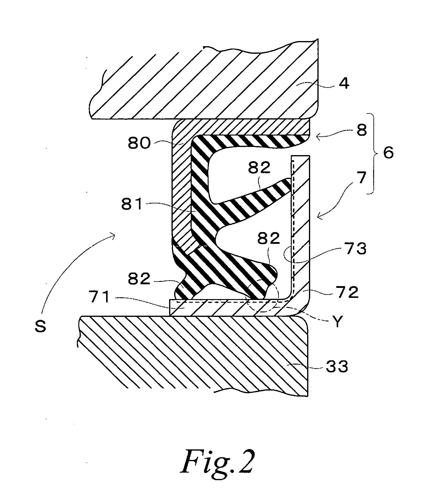
The present invention is a sealing device used to prevent water and dust from entering the wheel suspension of vehicles. The device includes a core member, a metal slinger, and an elastic seal member. The seal lip of the sealing device elastically and slidably contacts the slinger. The invention provides a sealing device that can reduce the rotary torque and the heat generation temperature of the seal lip. The slidably contacting treated surface of the slinger has a specific surface roughness to achieve these technical effects.

Problems solved by technology

When edges are formed concave and convex by roughening the slidably contacting face 730 as shown in FIG. 7a, there arises such a problem that the slidably contacting seal lip is worn away.

Method used


Image

  • Sealing device
  • Sealing device
  • Sealing device

Examples


experimental example

[0062]Slingers of sample A to sample H were prepared using metal material of SUS 430.

[0063]Sample A was a slinger without surface treatment and was made of rolled plate. Sample B was a slinger formed by cutting the above-mentioned metal material. Sample C was a slinger made of the above-mentioned metal material and the slidably contacting treated surface with the seal lip was processed with the above-mentioned concavity and convexity transferring treatment. Sample D to sample H were slingers of which slidably contacting treated surfaces with the seal lip were executed with a shot peening treatment. The shot peening treatment for the sample D to the sample H was executed such that minute solid particles of steel ball having a diameter of 40 to 200 μm were shot and hit at a speed more than 100 m / sec as mentioned above and the treated surface was cleaned with a cleaning water to remove the minute solid particles.

[0064]These 8 samples were checked with a rotary torque measuring instrume...


PUM


Abstract

A sealing device for sealing space between two members concentrically and relatively rotating comprising a core member fixedly fitted into one of the two members, a metal slinger fixedly fitted into the other of the two members, and an elastic seal member fixedly attached to the core member and having a seal lip which elastically and slidably contacts the slinger. The slinger has a slidably contacting treated surface for the seal lip as is processed such a surface-treatment as defined by the following parameters: arithmetic mean roughness Ra in the range from 0.5 μm to 1.5 μm, root-mean-square roughness Rq in the range from 0.6 μm to 2.0 μm, mean surface irregularity interval Sm in the range from 0.05 mm to 0.17 mm and peak count Pc (50%) in the range from 20 to 60.

Description

TECHNICAL FIELD[0001]The present invention relates to a sealing device comprising a core member fixedly fitted into one of two members rotating relatively and concentrically, a metal slinger fixedly fitted into the other of the two members, and an elastic seal member provided with a seal lip elastically and slidably contacting with the slinger and fixedly attached to the core member, thereby sealing a space between the two members.BACKGROUND ART[0002]A sealing device has been well known which is interposed between a stationary side member such as a bearing unit and a rotary side member in order to prevent water and dust from entering in the wheel suspension of vehicle wheels. Several measures have been recently taken so as to realize fuel efficient vehicles and the reduction of rotary torque is sought for the bearing unit. A seal lip is provided so as to elastically and slidably contact a slinger fixedly fitted to the rotary side member of the sealing device. If the force of seal li...

Claims


Application Information

Patent Timeline
Patent Type & Authority Applications(United States)
IPC IPC(8): F16J15/32F16C41/00F16C33/78F16J15/3232F16J15/328
CPCF16C41/007F16C2326/02F16J15/324F16C19/186F16J15/3264F16C33/7883F16J15/326
Inventor ISHIDA, KOKI
Owner UCHIYAMA MFG
Why Eureka
Eureka Blog
Learn More