Tube Arrangement and Crossbeam Having Such a Tube Arrangement

a tube arrangement and crossbeam technology, applied in the direction of dowels, furniture joining, rod connections, etc., can solve the problems of increased material outlay, insufficient flexural strength of the connection of the two tubes, and correspondingly limited linear weld seams between the two tubes

Active Publication Date: 2010-03-04
PROGRESS WERK OBERKIRCH
View PDF4 Cites 16 Cited by
  • Summary
  • Abstract
  • Description
  • Claims
  • Application Information

AI Technical Summary

Benefits of technology

[0043]Configuring the connection element in two parts has the advantage that tolerances in the longitudinal direction and the transverse direction of the tubes can also be compensated via the connection of the two parts to one another.

Problems solved by technology

If the crossbeam has a tube arrangement which is assembled from a plurality of tubes, there is basically a problem in the flexion-resistant connection of the individual tubes to one another.
If the two tubes have a round cross section, however, there is the problem that the two tubes are in contact in the overlap region solely along a generatrix, and the connection of the two tubes is correspondingly limited to a linear weld seam.
Such a connection of the two tubes, however, does not have sufficient flexural strength.
In order to achieve higher flexural strength with such a connection technique, the overlap region could be enlarged in the longitudinal direction, although, because of the greater length of the two tubes which is required, this may lead to an increased outlay in terms of material and therefore to a higher weight of the tube arrangement, this being undesirable when the tube arrangement is used for a crossbeam in a motor vehicle.
The gussets, although increasing the flexural strength of the connection of the two tubes, nevertheless have the disadvantage that, if the tube arrangement is used for a crossbeam, they impede the mounting of further structural parts of the crossbeam, in particular tie-up elements, for example for the instrument panel, in the region of the connection of the two tubes.
Furthermore, a connection by means of the connection elements described above has the further disadvantage that the flexural strength is sufficient in only two preferential directions which are determined by the planes of the connecting sheets or gussets, but may be insufficient in other spatial directions.
Sufficient flexural strength in a multiplicity of spatial directions would make it necessary, in such a connection technique, to mount further gussets which extend in different directions, which, however, further increases the weight and costs of the tube arrangement.
To be precise, in addition to the requirement for a low weight of a crossbeam for a motor vehicle, it must also be capable of being produced cost-effectively, thus entailing a further restriction in the possibilities for making a flexion-resistant connection of the two tubes.

Method used


Image

  • Tube Arrangement and Crossbeam Having Such a Tube Arrangement
  • Tube Arrangement and Crossbeam Having Such a Tube Arrangement
  • Tube Arrangement and Crossbeam Having Such a Tube Arrangement

Examples


Embodiment Construction

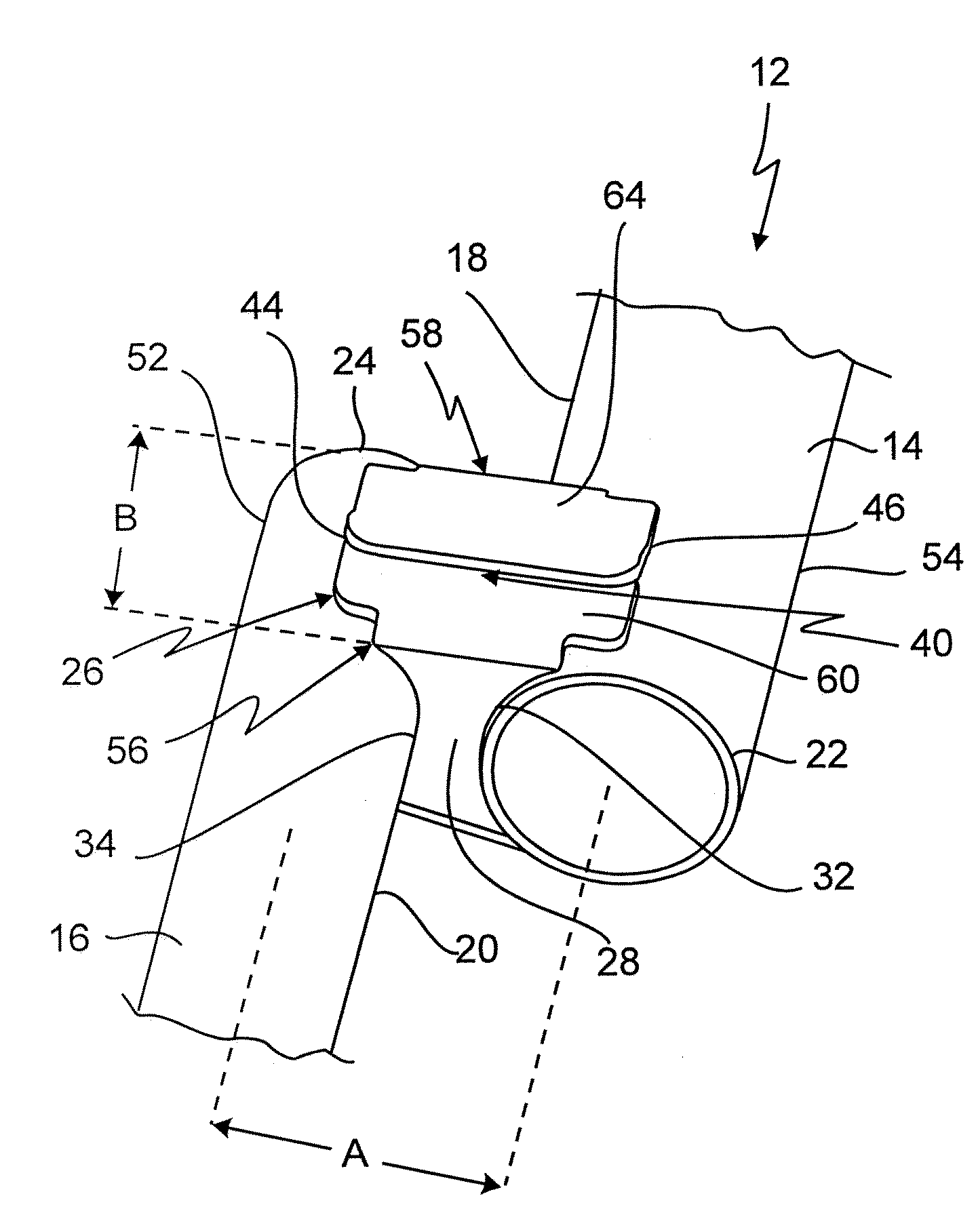
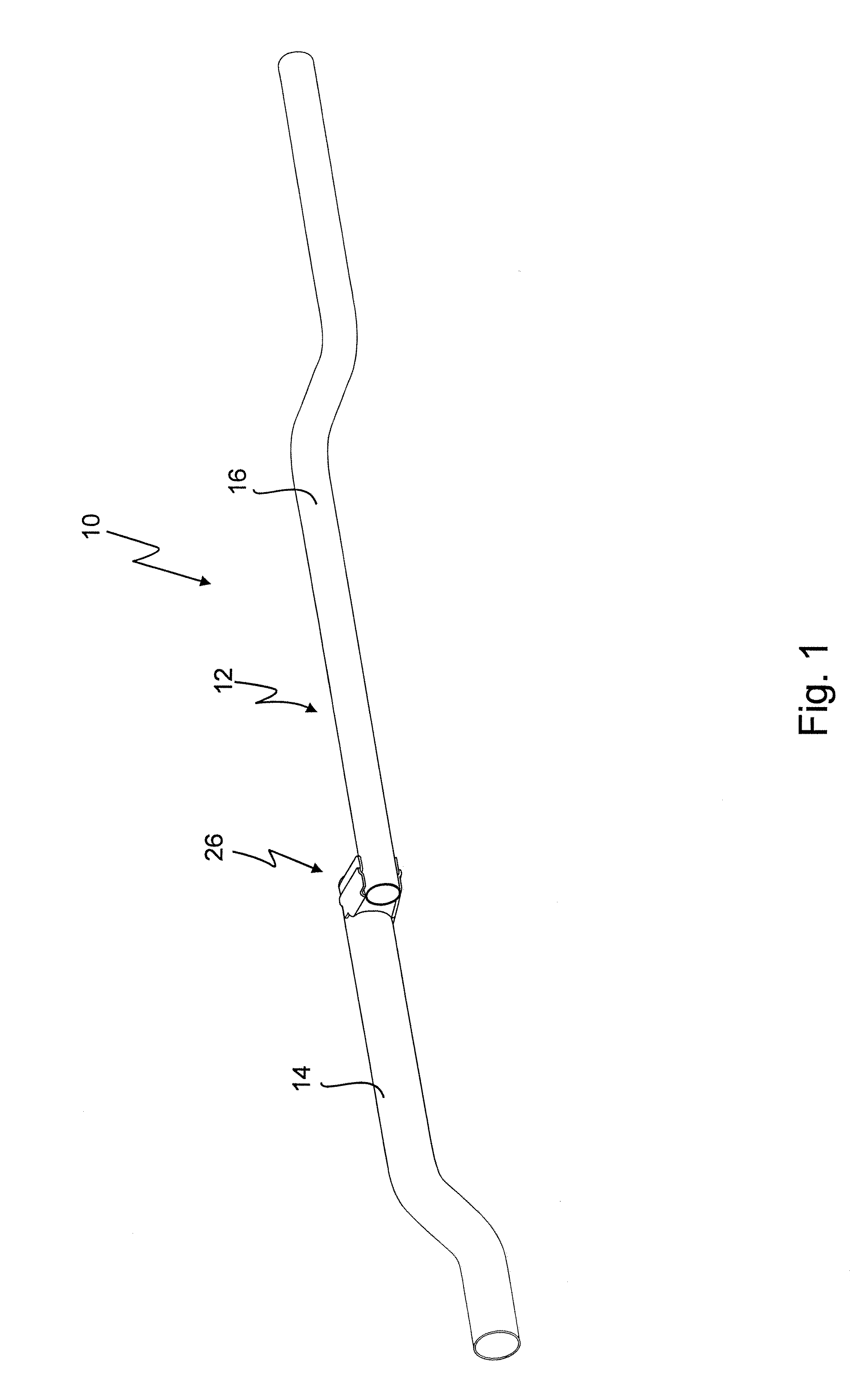
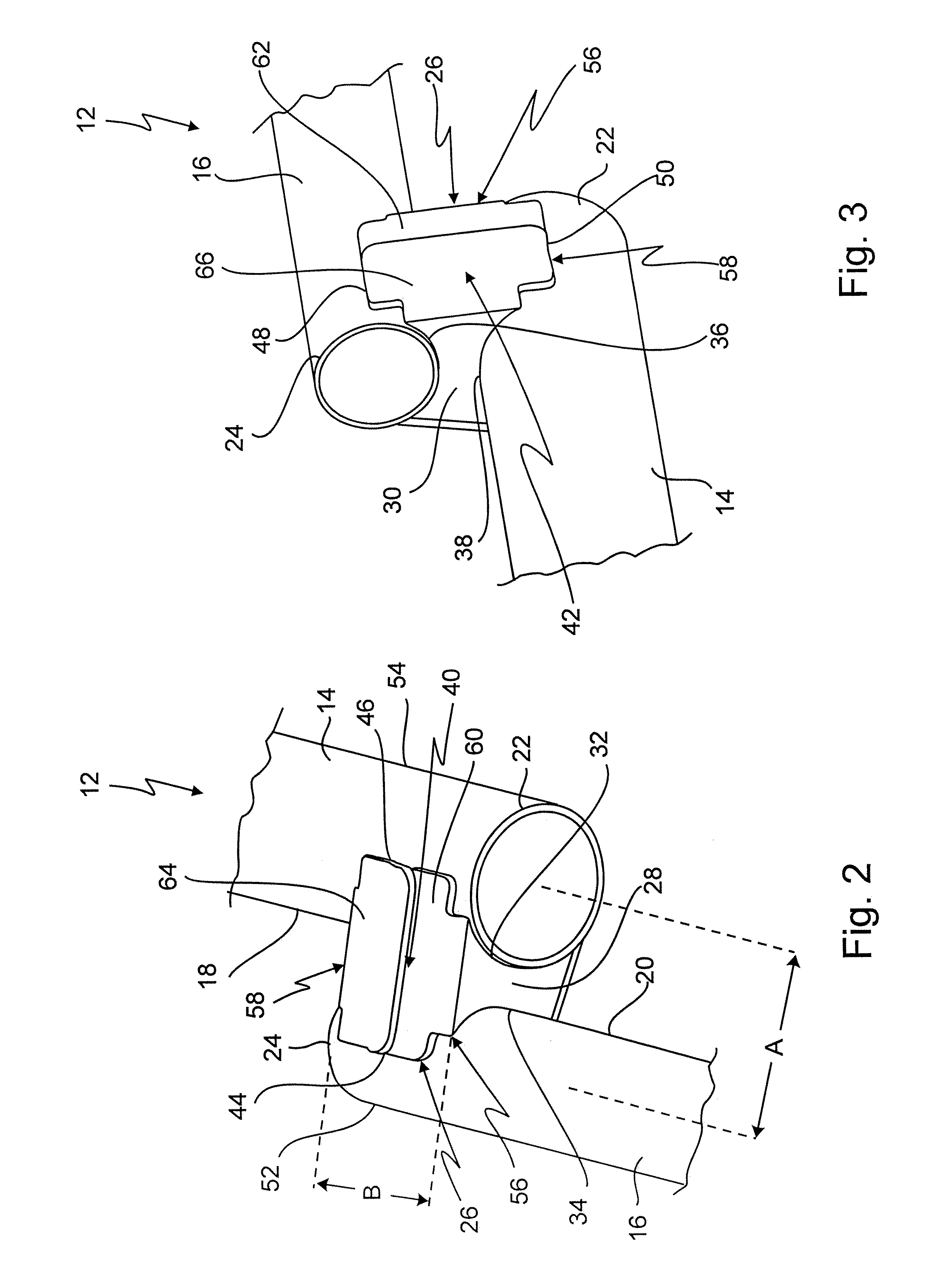
[0057]FIG. 1 illustrates a detail of a crossbeam given the general reference symbol 10. FIGS. 2 and 3 show particulars of the crossbeam 10. The crossbeam 10 serves as a body component of a motor vehicle and is installed in a motor vehicle between the A-pillars below the windscreen and receives the instrument panel.

[0058]The crossbeam 10 comprises a tube arrangement 12 which has a first tube 14 and a second tube 16.

[0059]In the exemplary embodiment shown, the first tube 14 and the second tube 16 are of circular cross section. It is to be understood that the first tube 14 and the second tube 16 may also have cross-sectional profiles deviating from a circular cross section. In the exemplary embodiment shown, the first tube 14 has a larger cross-sectional dimension than the second tube 16 or, in the case of the tubes 14 and 16 shown, which have a circular cross section, the first tube 14 has a larger outside diameter than the second tube 16.

[0060]The first tube 14 and the second tube 16...


PUM


Abstract

A tube arrangement comprises a first tube and at least one second tube, the first tube and the second tube being arranged in relation to one another with an offset transversely with respect to the longitudinal direction of the tubes and with a partial overlap region in the longitudinal direction of the tubes, so that a first end of the first tube is arranged at a side of the second tube and a second end of the second tube is arranged at a side of the first tube. The tube arrangement has, further, at least one connection element which fixedly connects the first tube and the second tube to one another in the overlap region. The connection element has a first end wall and a second end wall spaced apart from the first end wall in the longitudinal direction of the tubes, which end walls extend, in the overlap region, between the tubes transversely with respect to the longitudinal direction of the latter and are fixedly connected to these, and two longitudinal walls which are spaced apart from one another transversely with respect to the longitudinal direction and which extend in the longitudinal direction of the tubes from the first end wall to the second end wall and are fixedly connected to these.

Description

CROSS-REFERENCE TO FOREIGN APPLICATION[0001]The present application claims priority of German Patent Application No. 10 2008 045 914.3 filed on Aug. 28, 2008.BACKGROUND OF THE INVENTION[0002]The invention generally relates to tube arrangements, in particular to tube arrangements which form crossbeams or which form part of crossbeams, in particular crossbeams used in motor vehicles.[0003]Without any restriction in generality, the tube arrangement according to the invention is described by the example of its use as a crossbeam or as a component of a crossbeam for a motor vehicle. As part of the motor vehicle body, the crossbeam is arranged so as to run approximately horizontally between the A-pillars, as they are known, in the region below the windscreen. The crossbeam serves for fastening the instrument panel, moreover the crossbeam stiffening the instrument panel which usually consists of plastic and / or wooden parts.[0004]The crossbeam must have a high degree of flexural strength no...

Claims


Application Information

Patent Timeline
Patent Type & Authority Applications(United States)
IPC IPC(8): B62D25/08F16B7/00
CPCY10T403/55B62D25/145
Inventor SCHMIEDER, HANSJOERGJONCKHEERE, ROMARICOFFNER, ARNAUD
Owner PROGRESS WERK OBERKIRCH
Why Eureka
Try Eureka