LED regulation circuit and method

Inactive Publication Date: 2010-03-04
ZIPPY TECH
View PDF4 Cites 1 Cited by
  • Summary
  • Abstract
  • Description
  • Claims
  • Application Information

AI Technical Summary

Benefits of technology

[0004]The primary object of the present invention is to reduce heat generated by LEDs during operation to prevent excessive heat accumulation

Problems solved by technology

As a result, aside from generating light, a great amount of heat also is generated.
The heat is accumulated and could result in overheated and malfunction of the LED.
The fluorescent powder used on white light LEDs also could be degraded under heat and result in change of light c

Method used


Image

  • LED regulation circuit and method
  • LED regulation circuit and method
  • LED regulation circuit and method

Examples


Example

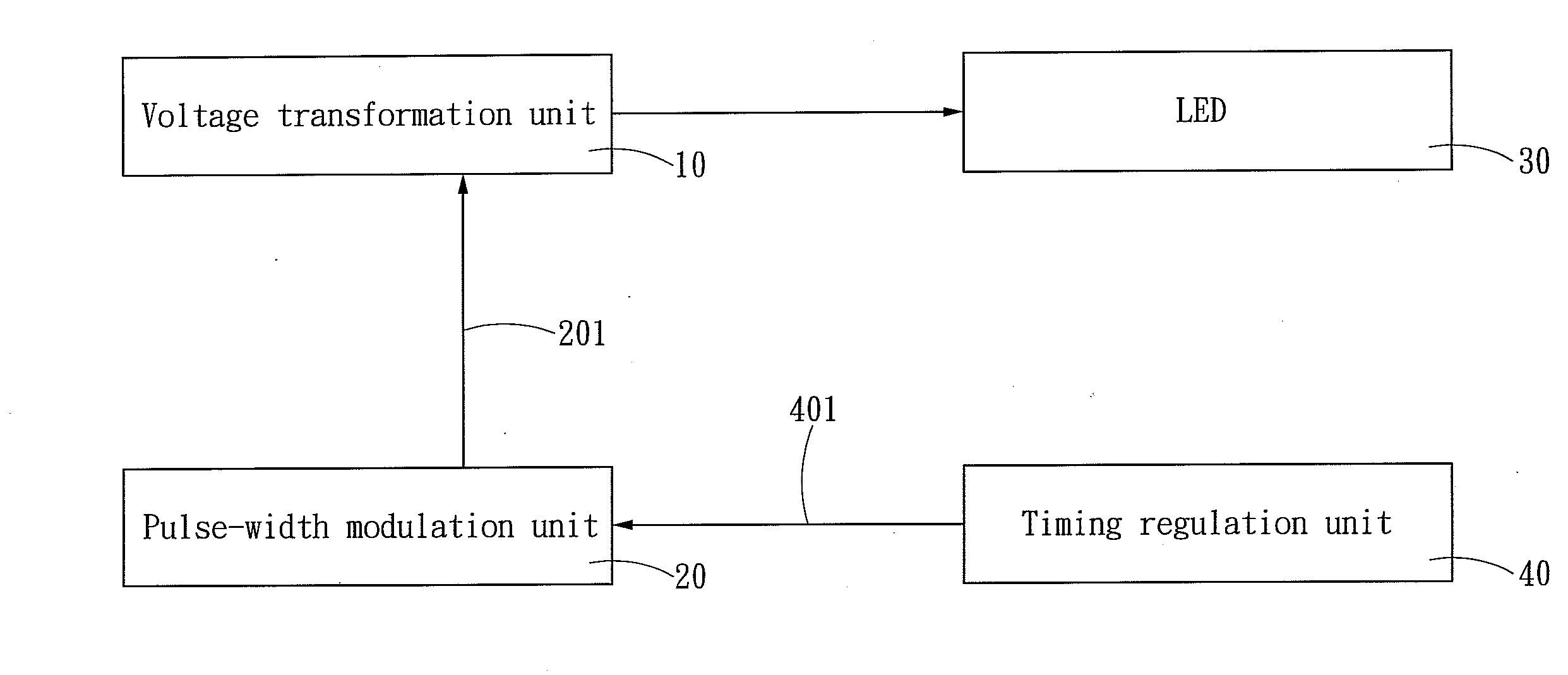
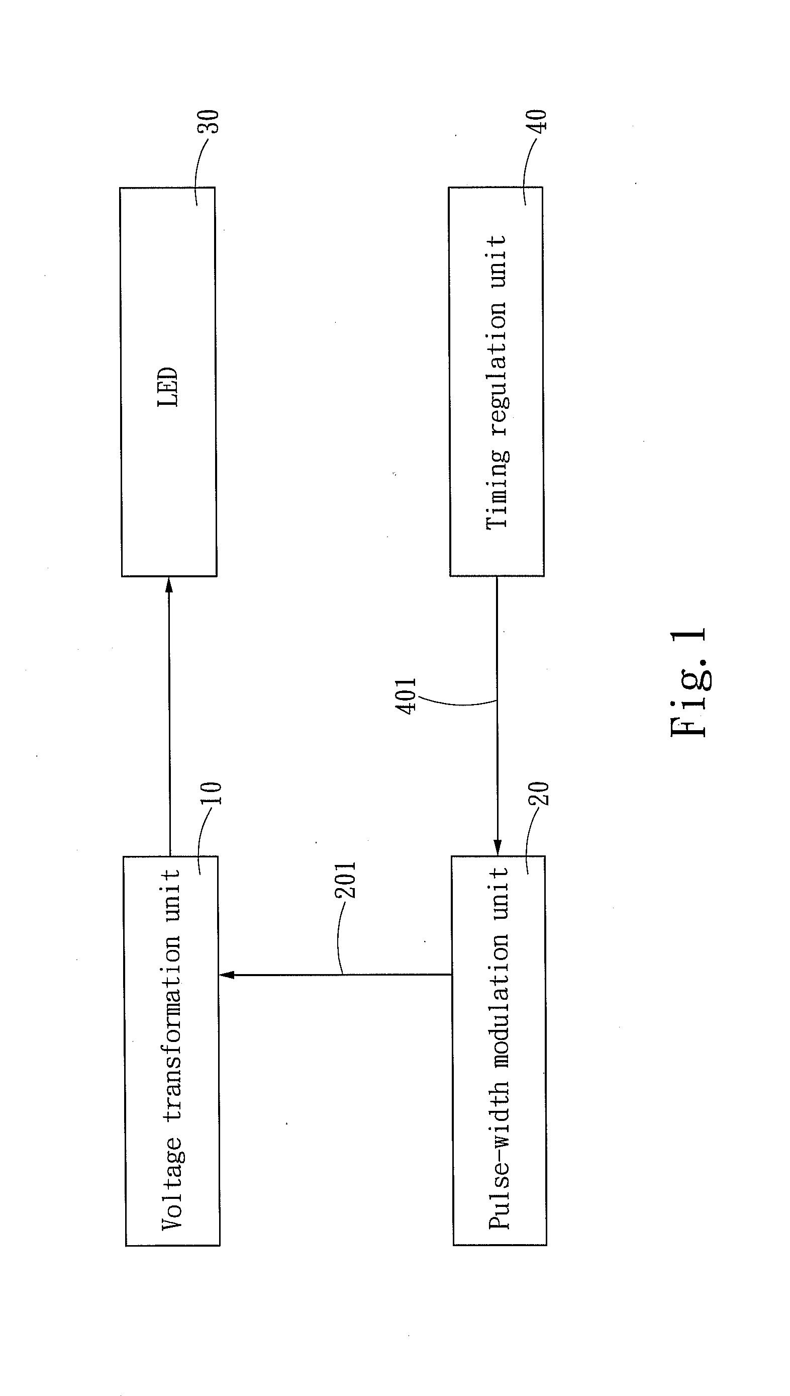
[0021]Please refer to FIG. 1 for the circuit block diagram of an embodiment of an LED regulation circuit of the invention. The regulation circuit includes a voltage transformation unit 10 to receive DC power and provide a constant current to drive at least one LED 30 and a pulse-width modulation unit 20 to generate a driving signal 201 to control the voltage transformation unit 10. The pulse-width modulation unit 20 is connected to a timing regulation unit 40 to receive a regulation signal 401 generated thereof.

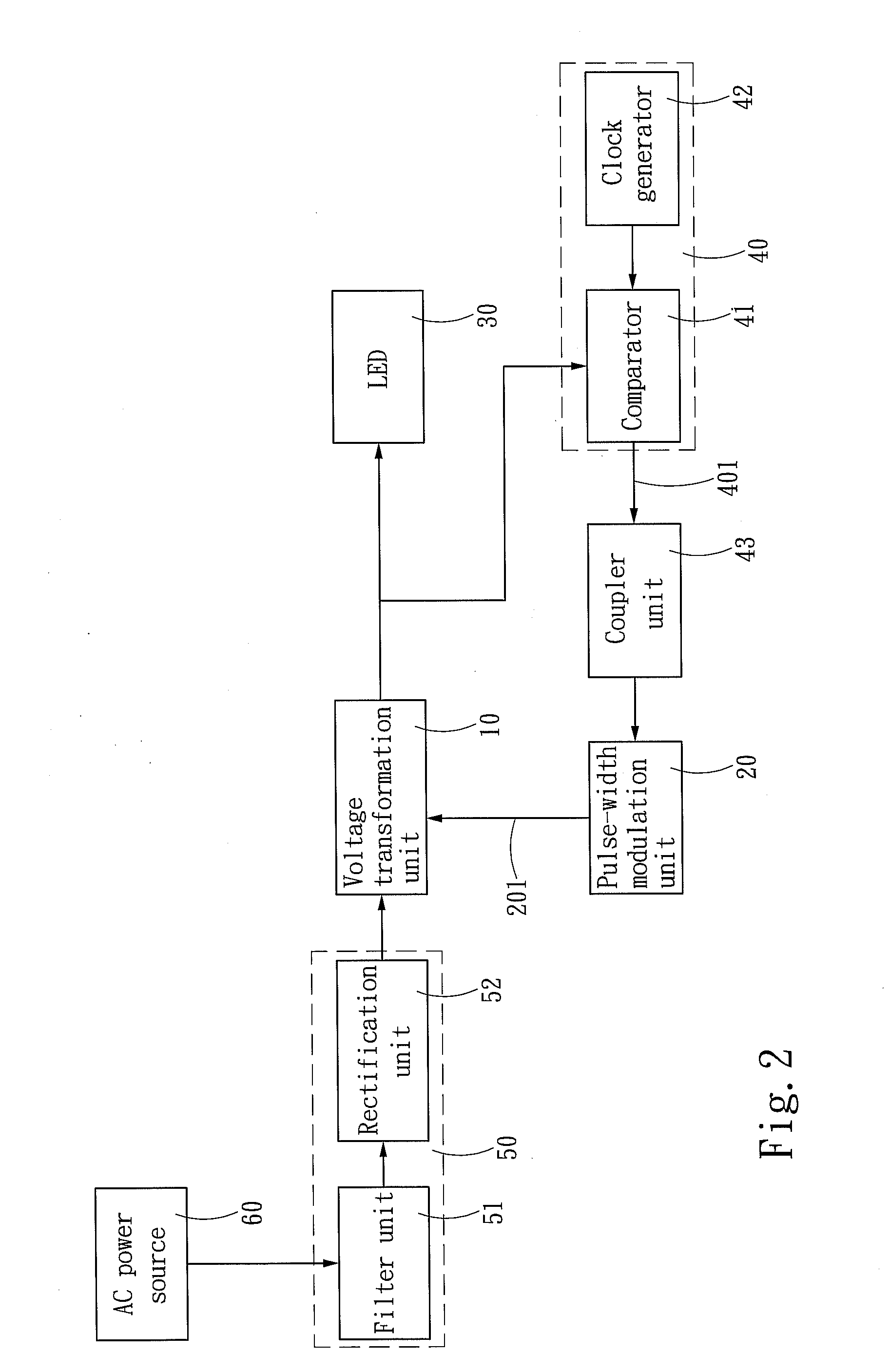
[0022]Refer to FIG. 2 for the circuit block diagram of another embodiment of the invention. The voltage transformation unit 10 is electrically connected to a rectification filter circuit 50 to receive AC power from an AC power source 60 (such as city power) and transform to DC power sending to the voltage transformation unit 10. The rectification filter unit 50 includes a filter unit 51 (such as an EMI filter) and a rectification unit 52. The timing regulation unit 40 has a c...


PUM


Abstract

An LED regulation circuit and method include a voltage transformation unit to receive DC power and provide a constant current to drive at least one LED and a pulse-width modulation unit to generate a driving signal to control the voltage transformation unit. The driving signal of the pulse-width modulation unit has an operation period. In the operation period, the driving signal drives the voltage transformation unit to output regular operation power. The pulse-width modulation unit is connected to a timing regulation unit which generates a regulation signal sent to the pulse-width modulation unit to regulate the operation period of the driving signal by adding a sleep period. In the sleep period, the driving signal lowers the power of the voltage transformation unit that drives the LED. Through alternately controlling the operation period and sleep period of the driving signal, continuous heat generation and heat accumulation can be reduced.

Description

FIELD OF THE INVENTION[0001]The present invention relates to a regulation circuit and method for electronic devices and particularly to an LED (light emitting diode) regulation circuit and method.BACKGROUND OF THE INVENTION[0002]LED provides many advantages over conventional lighting features such as a higher efficiency, longer life span and less likely to be damaged, thus is widely used in people's daily life nowadays. However, due to the LED is driven by a front end DC power supply to generate light and the DC power supply outputs a high current in a constant current mode as shown in FIG. 6, the LED receives the high current continuously. As a result, aside from generating light, a great amount of heat also is generated. The heat is accumulated and could result in overheated and malfunction of the LED. The fluorescent powder used on white light LEDs also could be degraded under heat and result in change of light color. All this seriously affects the brightness and durability of th...

Claims


Application Information

Patent Timeline
IPC IPC(8): H05B37/02
CPCH05B33/0818H05B45/37
Inventor CHUNG, CHIN-BIAU
Owner ZIPPY TECH
Why Eureka
Try Eureka