
Motor controller

a technology of motor controller and motor housing, which is applied in the direction of electric devices, gas pressure propulsion mounting, driver interactions, etc., can solve the problems of motor power factor and efficiency degradation, unnecessary power running and regenerative torque generation, and aging deterioration, so as to reduce unwanted charge or discharge and eliminate unwanted torque generation

Inactive Publication Date: 2010-03-04
HITACHI LTD
View PDF6 Cites 42 Cited by
  • Summary
  • Abstract
  • Description
  • Claims
  • Application Information

AI Technical Summary

Benefits of technology

[0004]In the aforementioned related art, the phase detection can be realized through relatively simple calculation by using only information inside the motor controller but because of calculation of a differential value of motor current during three-phase short-circuit, a larger number of A / D conversion operations than usual are needed, making the process sophisticated.
[0005]Accordingly, the present invention contemplates solving the aforementioned problem encountered in the conventional position estimation based on the calculation inside the motor controller and has for its object to provide a motor controller capable of preventing, in the presence of an error in magnetic pole position, the generation of unwanted power running and regenerative torque and the charge or discharge to or from the battery as well.
[0011]Then, in the motor controller, DC current set point calculation means is provided which calculates a set point of DC current for the inverter when the torque command value applied to the motor is zero and estimates an error in magnetic pole position of the motor by comparing the detected inverter DC current with the set point calculated by the DC current set point calculation means, thus correcting the magnetic pole position.
[0016]According to the present invention, when an error develops in a magnetic pole position detected by the motor revolution sensor, the positional error can be corrected, thereby realizing elimination of unwanted torque generation and reduction of unwanted charge or discharge to or from the battery.

Problems solved by technology

In controlling an AC motor provided with the magnetic pole position sensor, an error will often develops between a detected magnetic pole position and an actual magnetic pole position owing to positioning during assemblage of the magnetic pole position sensor, aging deterioration and detection accuracy of the magnetic pole position sensor per se as well.
When the phase of voltage is manipulated using the detected magnetic pole position in the presence of the error as above, the motor will suffer degradations in power factor and efficiency.
In addition, even if the torque command value to the motor is zero, a current will flow, so that unnecessary power running and regenerative torque are sometimes generated and the battery undergoes unwanted charge or discharge.

Method used


Image

  • Motor controller
  • Motor controller
  • Motor controller

Examples


first embodiment

[0029]this invention will now be described with reference to FIGS. 1 to 8.

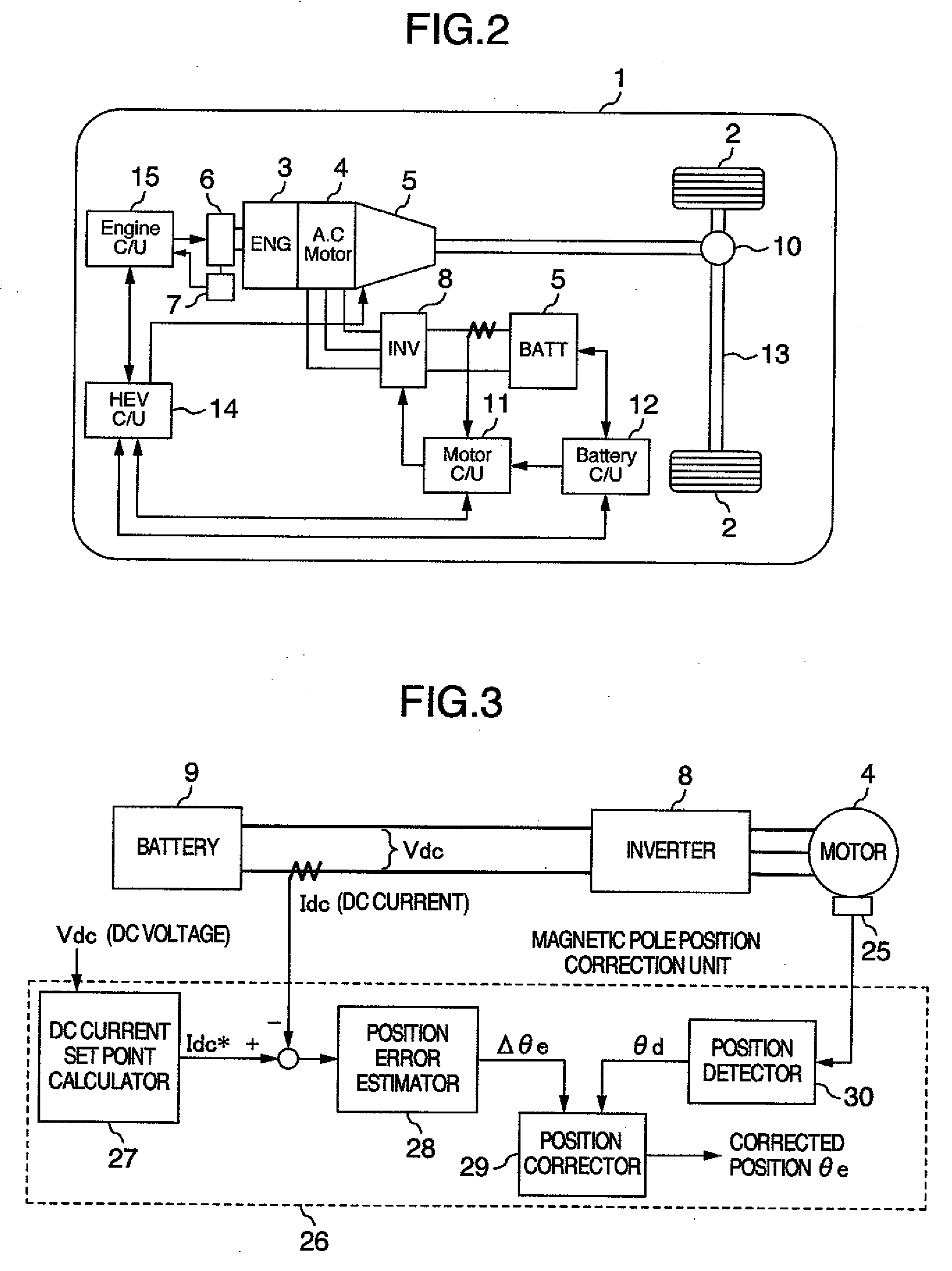
[0030]Firstly, reference will be made to FIG. 2 to describe the construction of a hybrid vehicle carrying a controller for a rotary machine and using an AC motor.

[0031]The hybrid vehicle, as generally designated by reference numeral 1, comprises an engine 3 and an AC motor 4. Drive force by the engine 3 is transmitted to front wheels 2 via a transmission 5 and an axle 13, driving the front wheels 2. The output of the engine 3 is controlled with an electronic control throttle 6 driven by commands from an engine control unit 15. The electronic control throttle 6 is provided with an accelerator opening sensor 7 so as to detect an accelerator opening. The output of the engine 3 not only drives the front wheels 2 but also drives sometimes the AC motor 4. Drive force by the AC motor 4 is transmitted to the driving wheels 2 via a differential gear 10 and the axle 13, driving the driving wheels 2. Exemplified in FIG. ...


PUM


Abstract

When the torque command value is zero, a set point of DC current for an inverter is calculated to obtain a difference between the set point and a detected DC current so that an error in magnetic pole position may be estimated and corrected. By correcting the magnetic pole position, unwanted power running and regenerative torque of the motor can be avoided and unnecessary charge or discharge to or from a battery can be prevented.

Description

BACKGROUND OF THE INVENTION[0001]The present invention relates to motor controllers and more particularly to a method of controlling a rotary machine used in a hybrid vehicle and a controller therefor.[0002]In the hybrid vehicle or an electro-mobile using a motor in the drive system of a vehicle, for the sake of controlling the torque or revolution speed of the motor (for example, a DC brushless motor), the phase of voltage applied to an armature needs to be controlled in accordance with the position of a magnetic pole of a rotor. Accordingly, in this type of motor (DC brushless motor), a magnetic pole position sensor for detection of the rotor's magnetic position is provided so that the phase of the voltage applied to the armature may be manipulated in accordance with a magnetic pole position detected by the magnetic pole position sensor. The magnetic pole position sensor as above is constructed of a resolver, an encoder and a Hall device. In controlling an AC motor provided with t...

Claims


Application Information

Patent Timeline
IPC IPC(8): H02P6/16H02P27/04B60K6/485B60L9/18B60L50/16H02P6/06H02P6/08H02P6/28H02P21/00H02P21/14H02P21/22H02P23/14H02P27/08
CPCB60K6/48Y02T10/70B60L3/0046B60L3/0061B60L3/0092B60L3/04B60L11/14B60L15/025B60L2210/20B60L2220/14B60L2220/16B60L2250/16B60W10/06B60W10/08B60W20/00H02P6/142H02P21/02H02P21/146Y02T10/6221Y02T10/6286Y02T10/643Y02T10/7077Y02T10/725B60L3/0038B60W2510/244B60W2710/086B60L50/16B60L58/15H02P6/15H02P21/18Y02T10/62Y02T10/64Y02T10/7072Y02T10/72B60W20/10B60W2510/24
Inventor IZUMI, SHIHOKANEKO, SATORUNIHEI, HIDEKI
Owner HITACHI LTD
Features
  • Generate Ideas
  • Intellectual Property
  • Life Sciences
  • Materials
  • Tech Scout
  • Unparalleled Data Quality
  • Higher Quality Content
  • 60% Fewer Hallucinations
Learn More