
Integrated circuit device and electronic equipment

a technology of integrated circuits and electronic equipment, applied in the direction of electric digital data processing, instruments, computing, etc., can solve the problems of affecting the accuracy of data voltage output, the inability to accurately present grayscales, and the inability to drive data voltage supply lines faster, so as to achieve the desired grayscale voltage. a relatively long time for each data voltag

Active Publication Date: 2010-03-04
SEIKO EPSON CORP
View PDF4 Cites 16 Cited by
  • Summary
  • Abstract
  • Description
  • Claims
  • Application Information

AI Technical Summary

Benefits of technology

[0011]In accordance with an advantage of some aspects of embodiments of the present invention, it is possible to provide integrated circuit devices and electronic equipment that are capable of correcting differences in data voltages in real-time.
[0014]According to the embodiment of the invention described above, correction data for correcting differences in data voltages to be outputted from the data line driving circuits are obtained. By this, even when the data line driving circuits have differences in data voltages due to manufacturing-derived differences, data voltages corresponding to image data can be outputted with high accuracy and the image quality can be improved. Also, in accordance with the embodiment of the invention, the first mode is executed in one horizontal scanning period in a non-display period in a vertical scanning period. As a result, correction data can be calculated in real time, and deterioration of the image quality can be prevented even when the output characteristics of the data line driving circuits change due to heat or other external factors. Furthermore, by executing the first mode in non-display periods, correction data can be calculated without affecting image display.
[0018]By this, the image data can be corrected based on the initial values even during a period until correction data are calculated by the first mode. For this reason, the image display can be started in a state in which differences in data voltages are corrected, and therefore the image quality at the start of image display can be improved.
[0032]According to the aspect of the embodiment of the invention described above, correction data is calculated, using currently obtained correction data and previously obtained correction data. Therefore, even when differences in data voltages are not accurately measured due to noise or other influences, the use of the previously obtained correction data can prevent the presently obtained data from becoming inaccurate.
[0034]In this manner, the amount of change in correction data is limited within a predetermined range of positive or negative values by using the previously calculated correction data. By this, abrupt changes in correction data can be suppressed, and deterioration of the image quality can be prevented even when differences in data voltages cannot be accurately measured due to noise or other influences.

Problems solved by technology

Concretely, the greater the number of grayscale levels, the smaller the grayscale voltage for each grayscale level, such that the grayscales would not be correctly presented if a slight error occurs in the driving voltage of the driver.
However, the higher the definition of a liquid crystal panel, the faster the drive data voltage supply lines need to be driven.
The method described in Patent Document 1 uses DAC outputs with higher output impedance, compared to those of the operation amplifiers, and therefore entails a problem in that it takes a relatively long time for each data voltage to reach a desired grayscale voltage.
However, the characteristics of liquid crystal panels and drivers deteriorate with passing of time after having been shipped out.
The method described in Patent Document 2 uses correction data adjusted at the time of manufacturing liquid crystal panels for the correction, and therefore entails a problem in that changes in the characteristics that occur after shipping cannot be accommodated.

Method used


Image

  • Integrated circuit device and electronic equipment
  • Integrated circuit device and electronic equipment
  • Integrated circuit device and electronic equipment

Examples


Embodiment Construction

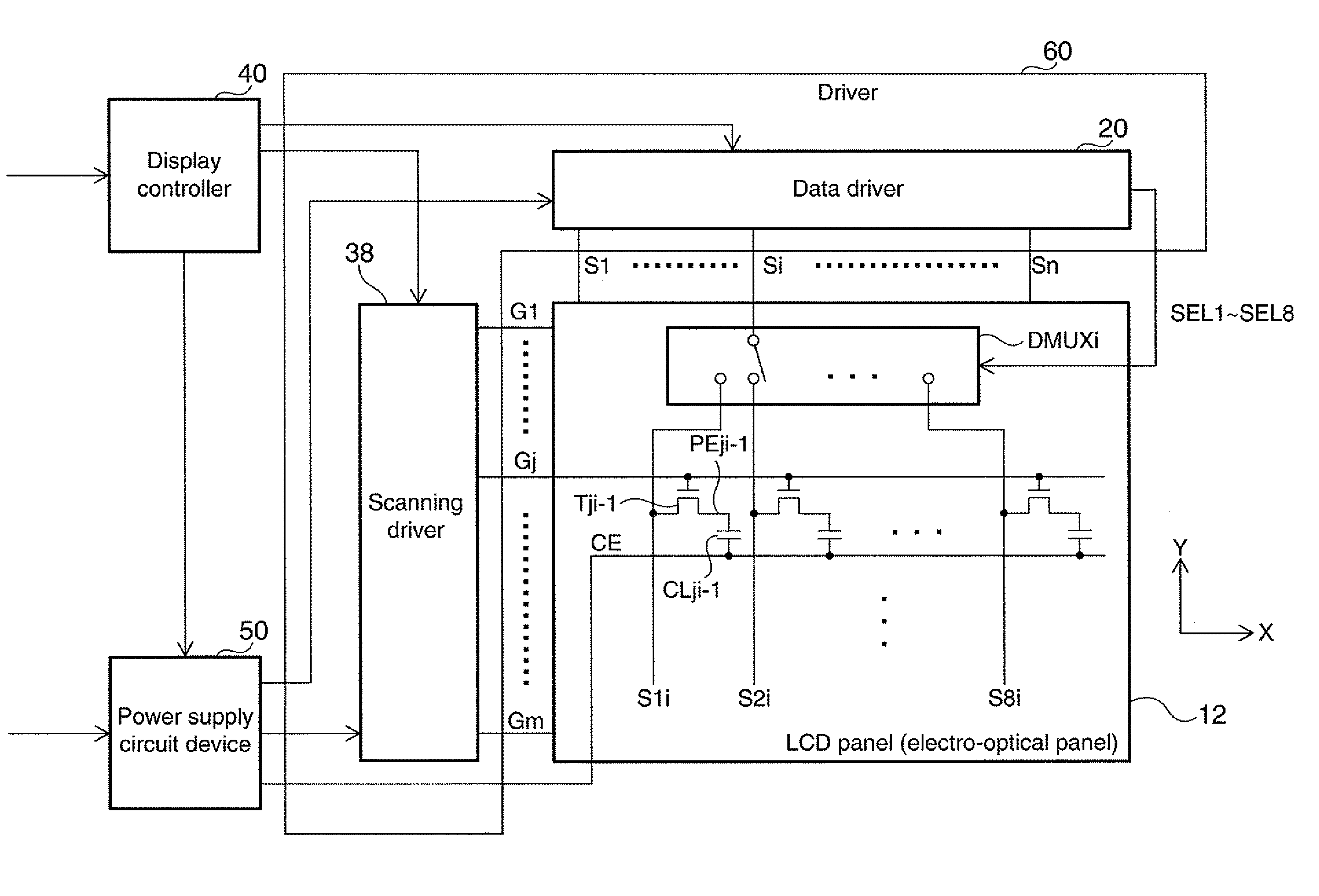
[0053]Preferred embodiments of the invention are described below in detail. It is noted that embodiments to be described below would not unduly limit contents of the invention described in the scope of the patent claims, and it should be noted that not all of the components described in accordance with the embodiments would necessarily be essential as means for solution provided by the invention.

[0054]1. Data Voltage Correction Circuit

[0055]1.1. Exemplary Structure

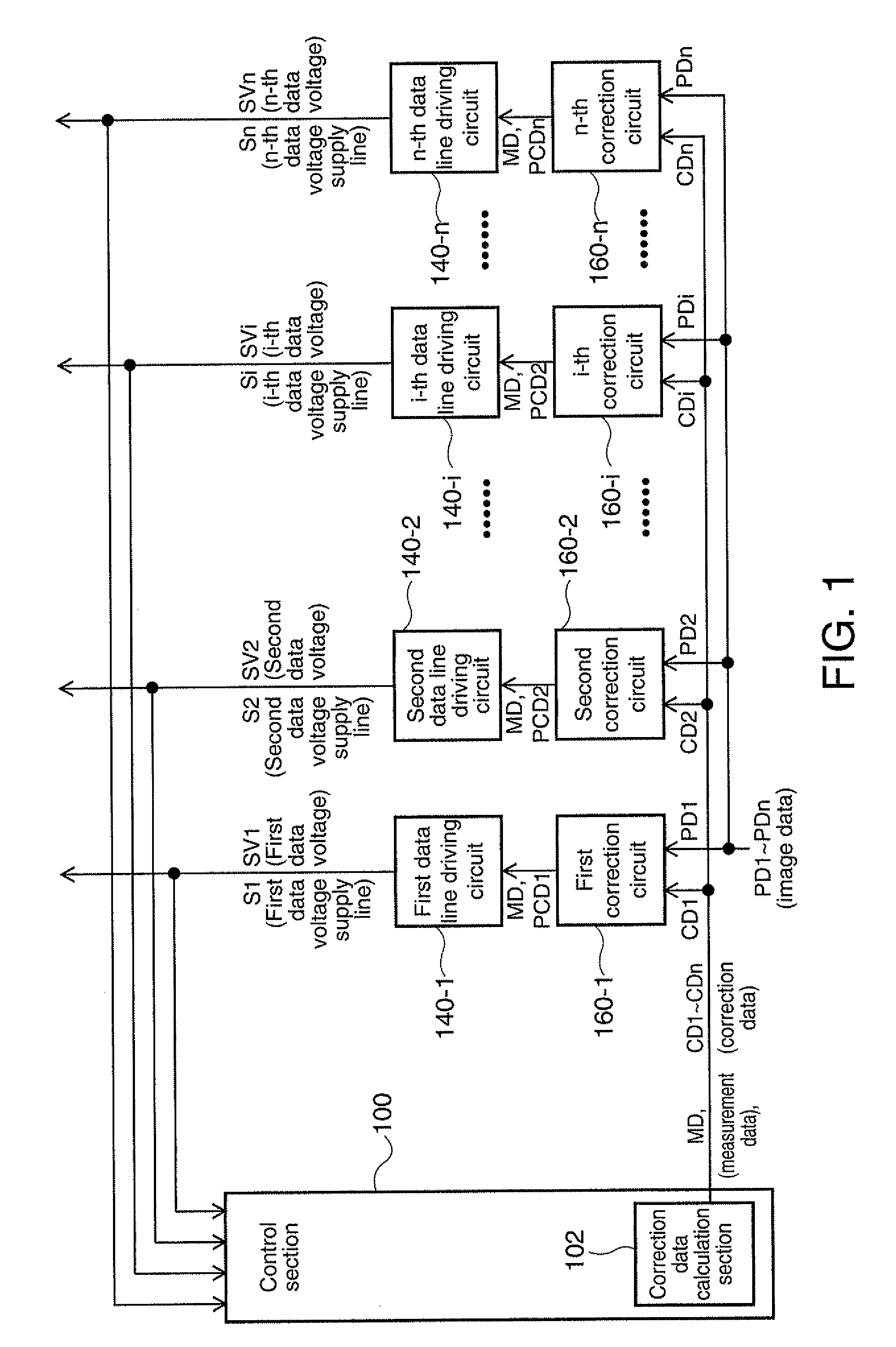
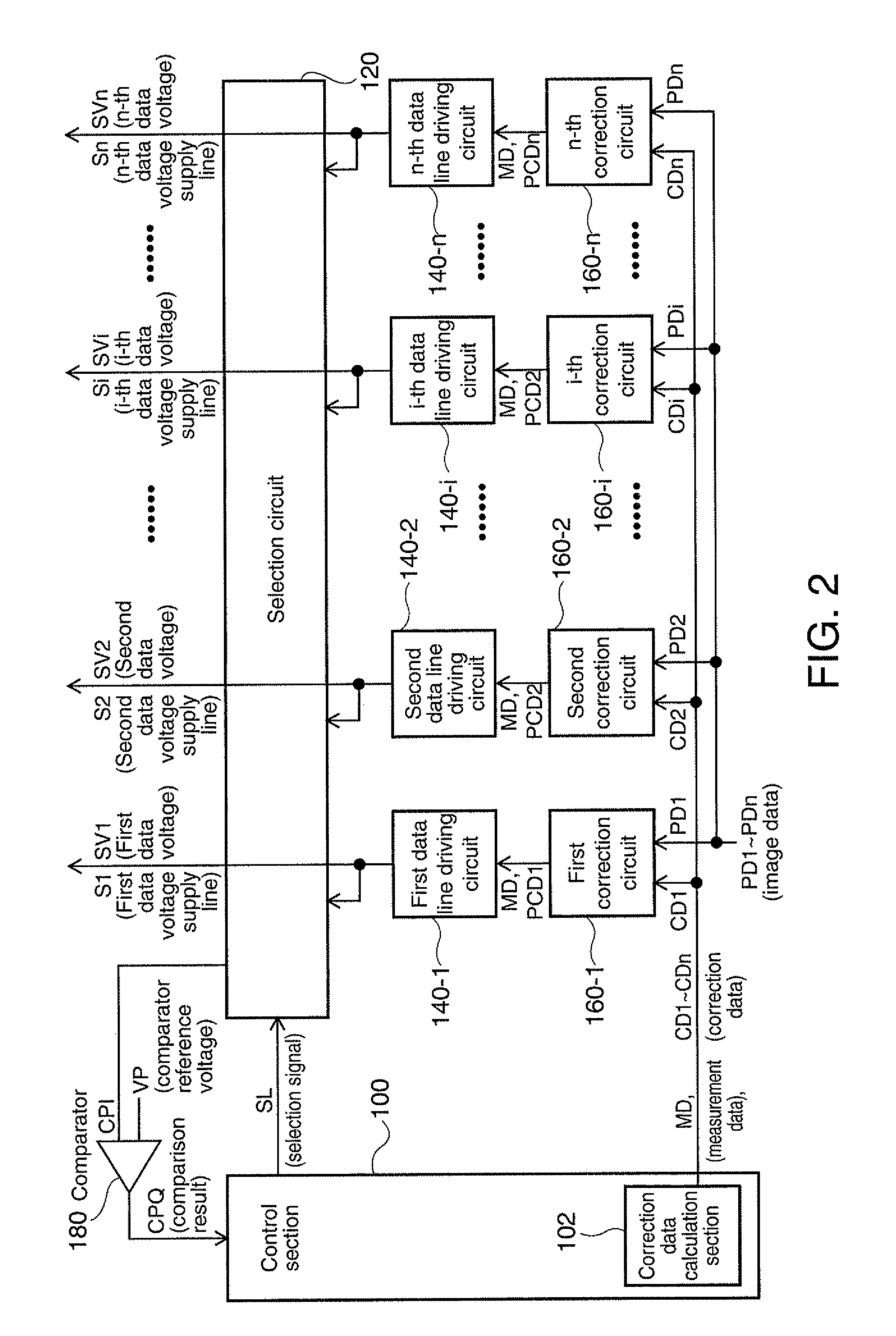
[0056]FIG. 1 shows an example of the basic structure of the embodiment. The exemplary structure shown in FIG. 1 includes the first through n-th data line driving circuits 140-1 through 140-n (a plurality of data line driving circuits), correction circuits 160-1 through 160-n (a plurality of correction circuits), and a control section 100. The control section 100 includes a correction data calculation section 102. It is noted that it is possible to make many changes, such as, omitting a portion of the components, adding oth...


PUM


Abstract

An integrated circuit device includes: a plurality of data line driving circuits that drive a plurality of data voltage supply lines; and a correction data calculation section that calculates correction data for correcting differences in data voltages outputted from the plurality of data line driving circuits, wherein the correction data calculation section executes, in one horizontal scanning period in a non-display period in a vertical scanning period, a first mode to obtain the correction data corresponding to a data line driving circuit to be corrected among the plurality of data line driving circuits.

Description

[0001]The entire disclosure of Japanese Patent Application No. 2008-226369, filed Sep. 3, 2008 and Japanese Patent Application No. 2009-160785, filed Jul. 7, 2009 are expressly incorporated by reference herein.BACKGROUND[0002]1. Technical Field[0003]An aspect of the present invention relates to integrated circuit devices and electronic equipment.[0004]2. Related Art[0005]High definition imaging technology, such as, high-vision imaging technology has become popular in recent years, and with such a technological trend, higher definition and greater multi-grayscale displays have been achieved in display equipment (electronic equipment) such as liquid crystal projectors and the like. Such display equipment with greater multi-grayscale requires analog circuits with high accuracy in their drivers to drive liquid crystal panels (electro-optical panels).[0006]Concretely, the greater the number of grayscale levels, the smaller the grayscale voltage for each grayscale level, such that the gra...

Claims


Application Information

Patent Timeline
Patent Type & Authority Applications(United States)
IPC IPC(8): G06F3/038
CPCG09G3/3688G09G2320/0233G09G2310/0297
Inventor MORITA, AKIRA
Owner SEIKO EPSON CORP
Learn More