Endoscope apparatus

a technology of endoscope and endoscope, which is applied in the field of endoscope apparatus, can solve the problems of loss of light, inability to observe two directions simultaneously, complex structure, etc., and achieve the effects of reducing the diameter of the stent, simple structure and reducing the burden on the examination subj

Active Publication Date: 2010-03-04
OLYMPUS CORP
View PDF7 Cites 148 Cited by
  • Summary
  • Abstract
  • Description
  • Claims
  • Application Information

AI Technical Summary

Benefits of technology

[0015]The present invention has been conceived in light of the circumstances described above, and an object thereof is to provide an endoscope apparatus in which the distal end of an inserted portion, having a simple structure, can be reduced in diameter, which can reduce the loss of light incident from the body cavity, and which can observe light from two different directions simultaneously and in a separated fashion.
[0035]According to the present invention, an advantage is afforded in that, the distal end of the inserted portion, having a simple structure, can be reduced in diameter, loss of light incident from the body cavity can be reduced, and light from two different directions can be observed simultaneously and in a separated fashion.

Problems solved by technology

However, the endoscope apparatus disclosed in Patent Document 1 has a drawback in that, because it acquires light from two directions by switching the mirror, it cannot observe two directions simultaneously.
Also, the endoscope apparatus disclosed in Patent Document 2 has a problem in that the structure is complex because it has separate image-forming optical systems for imaging light from two directions.
The endoscope apparatus disclosed in Patent Document 3 has a problem in that loss light occurs, making it difficult to obtain a bright image, because, of the light incident from the longitudinal axial direction and the radial direction of the inserted portion, only light beams having specific polarization directions are respectively transmitted.
Furthermore, the endoscope apparatus disclosed in Patent Document 4 also has a problem in that, regarding the light incident from the longitudinal axial direction, light passing through a central hole in the quadrangular pyramid mirror is observed, and therefore, the acquired light is restricted by the central hole, which causes loss of light.

Method used


Image

  • Endoscope apparatus
  • Endoscope apparatus
  • Endoscope apparatus

Examples


Embodiment Construction

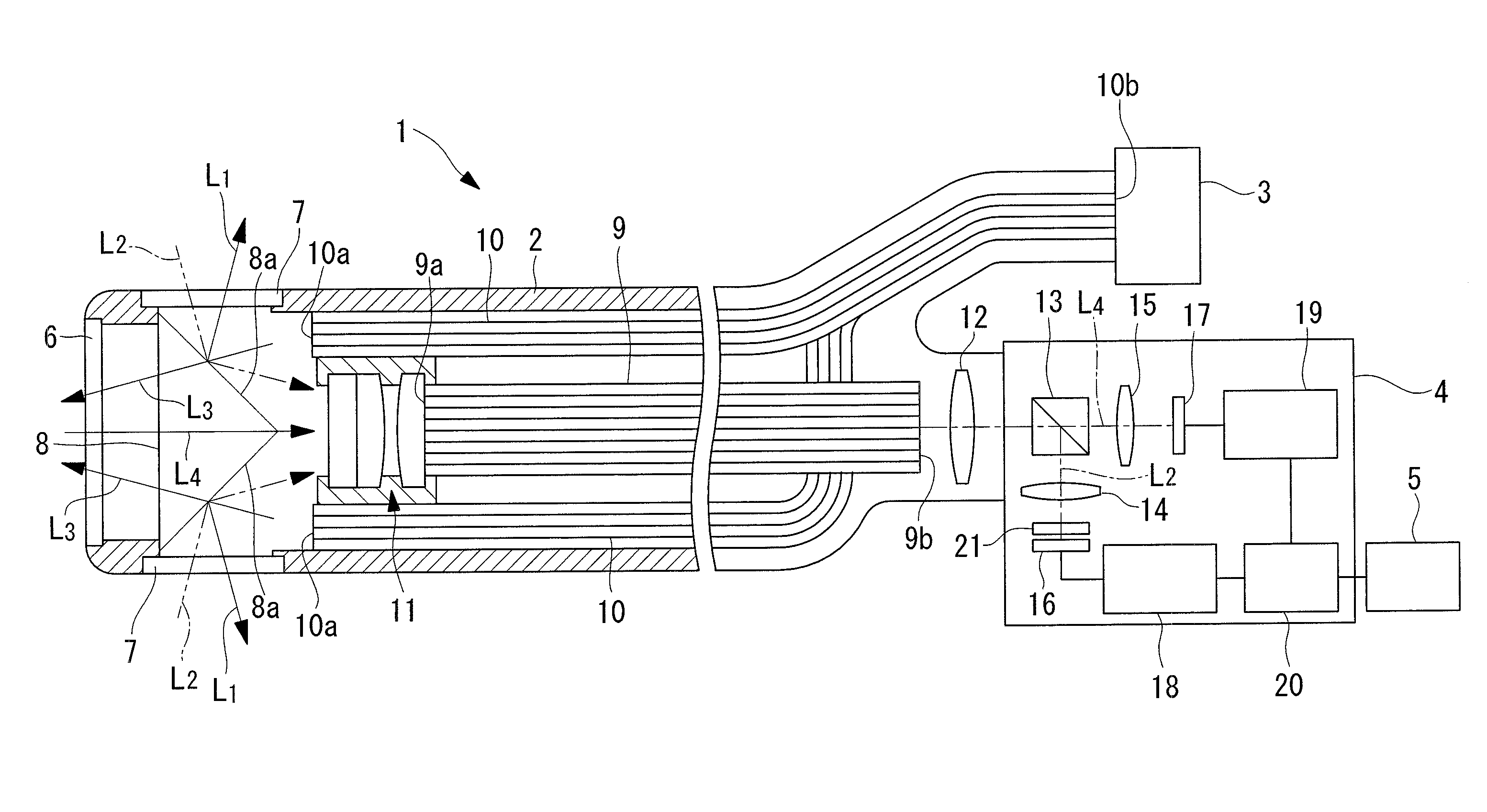
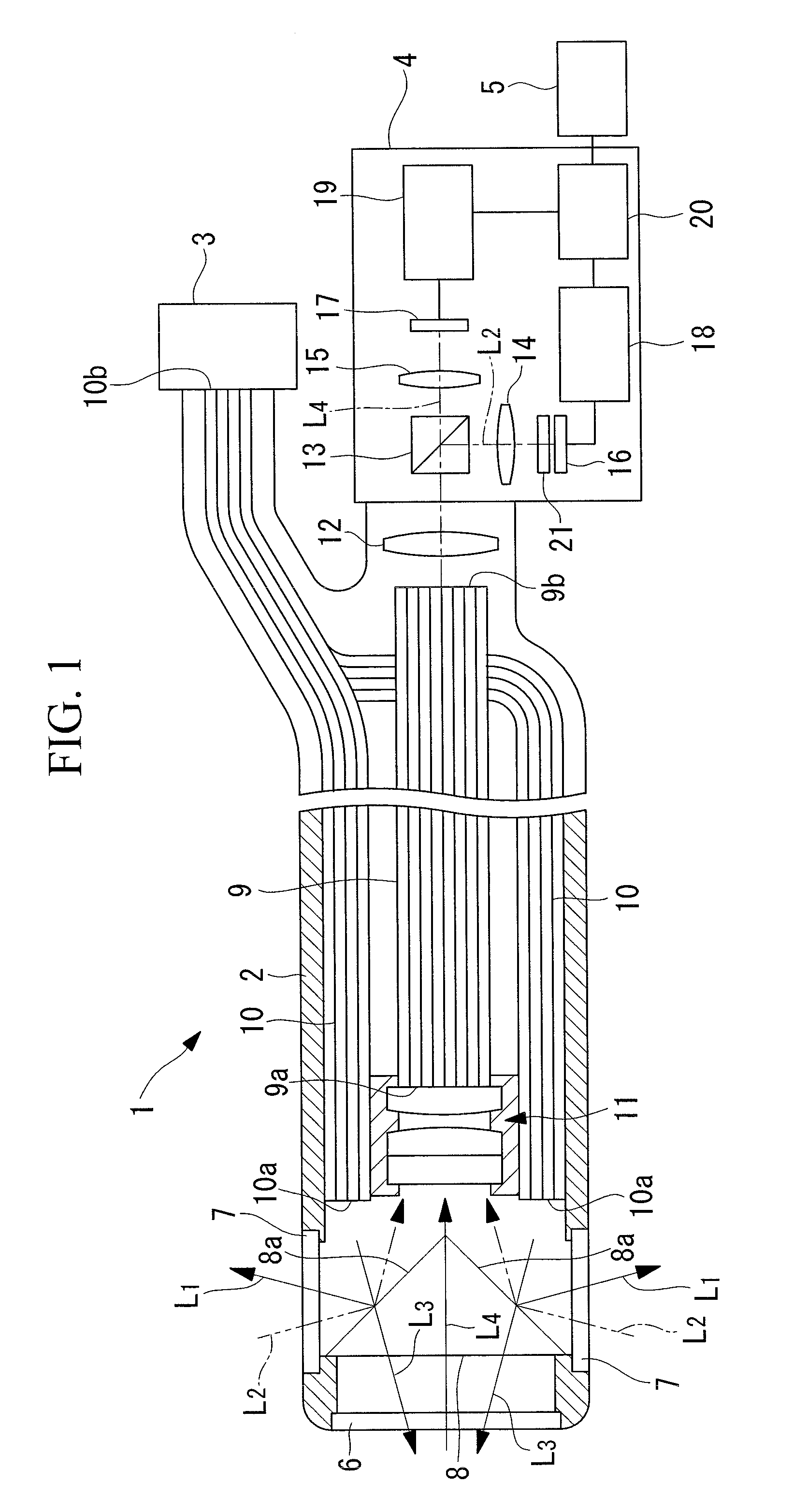
[0066]An endoscope apparatus 1 according to an embodiment of the present invention will be described below with reference to FIGS. 1 to 3.

[0067]As shown in FIG. 1, the endoscope apparatus 1 according to this embodiment includes a long, narrow inserted portion 2 that is inserted inside a body cavity, a light source 3 connected at the base end of the inserted portion 2, an image-acquisition unit 4 connected to the same base end of the inserted portion 2, and a display unit 5 connected to the image-acquisition unit 4.

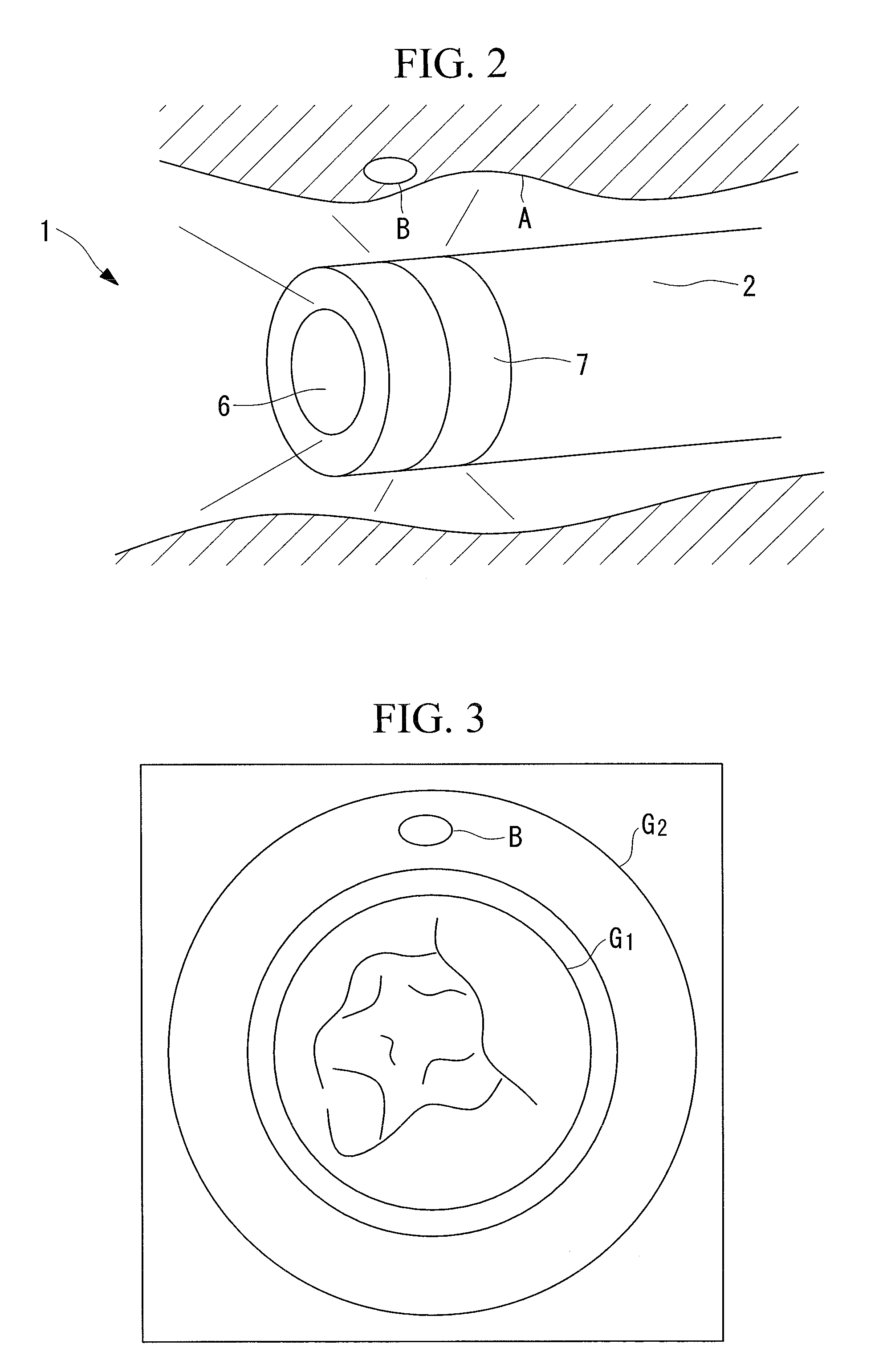
[0068]The inserted portion 2 includes transparent windows 6 and 7 in the distal end face and around the entire outer circumference of the distal end portion thereof. A cone-shaped dichroic conical mirror (first dichroic mirror) 8 is disposed in the distal end portion of the inserted portion 2 with its bottom surface facing the window 6 at the distal end of the inserted portion 2. The dichroic mirror 8 has optical thin films (not shown in the drawing), formed on a conical s...


PUM


Abstract

The distal end of an inserted portion, having a simple structure, is reduced in diameter, loss of light incident from a body cavity is reduced, and light from two different directions is observed simultaneously and in a separated fashion. Provided is an endoscope apparatus (1) including an inserted portion (2) to be inserted inside a body cavity; a first dichroic mirror (8), disposed in a distal end portion of the inserted portion (2), that transmits light (L4) in a first wavelength band, which is incident from a longitudinal axial direction and that deflects light (L2) in a second wavelength band, which is incident from a radial direction, in the longitudinal axial direction, thereby multiplexing it with the light (L4) in the first wavelength band; a second dichroic mirror (13) that splits the light (L2, L4) multiplexed by the first dichroic mirror (8) into each wavelength band; and two image-acquisition units (16, 17) that respectively acquire the light (L2, L4) in the first and second wavelength bands split by the second dichroic mirror (13).

Description

TECHNICAL FIELD[0001]The present invention relates to an endoscope apparatus.BACKGROUND ART[0002]In the related art, there are known endoscopes apparatuses that can observe light incident from a distal end face of an inserted portion and light incident from radially outward (for example, see Patent Documents 1 to 4).[0003]The endoscope apparatus in Patent Document 1 performs observation by switching between light from the longitudinal axial direction and the radial direction by means of a switchable mirror.[0004]The endoscope apparatus in Patent Document 2 employs a structure for making light in a common wavelength band incident from the longitudinal direction and radial direction of the inserted portion via separate image-forming optical systems.[0005]The endoscope apparatus in Patent Document 3 perform observation by multiplexing light with different polarization directions by using a polarizing prism.[0006]The endoscope apparatus in Patent Document 4 performs simultaneous observa...

Claims


Application Information

Patent Timeline
Patent Type & Authority Applications(United States)
IPC IPC(8): H04N7/18
CPCA61B1/00096A61B1/00181A61B1/041A61B1/00165A61B1/043A61B1/07A61B1/0638A61B1/0625
Inventor WATANABE, TOSHIAKIKARASAWA, RYO
Owner OLYMPUS CORP
Why Eureka
Try Eureka