Optical arrangement

Inactive Publication Date: 2010-03-04
KONINKLIJKE PHILIPS ELECTRONICS NV
View PDF11 Cites 84 Cited by
  • Summary
  • Abstract
  • Description
  • Claims
  • Application Information

AI Technical Summary

Benefits of technology

[0008]Hence, in view of the above, it is an object of the present invention to overcome or at least alleviate problems in the prior art and/or to provide an alternative luminaire arrangement. A specif

Problems solved by technology

However, one issue with LED lighting is the provision of warm white light.
However, a problem with such a solution is that the phosphor has to withstand the temperature of the LED and the light flux at the same time.
The result is often that this type of LED and phosphor solution does not meet the lifetime requirements necessary.
A remedy to this particular problem is to avoid attaching the phosphor directly to the LED chip, but this results in other side effects and problems.
For example, remote phosphor solutions of this kind result in that many solutions developed for ordinary LEDs are no longer compatible,

Method used


Image

  • Optical arrangement
  • Optical arrangement
  • Optical arrangement

Examples


first embodiment

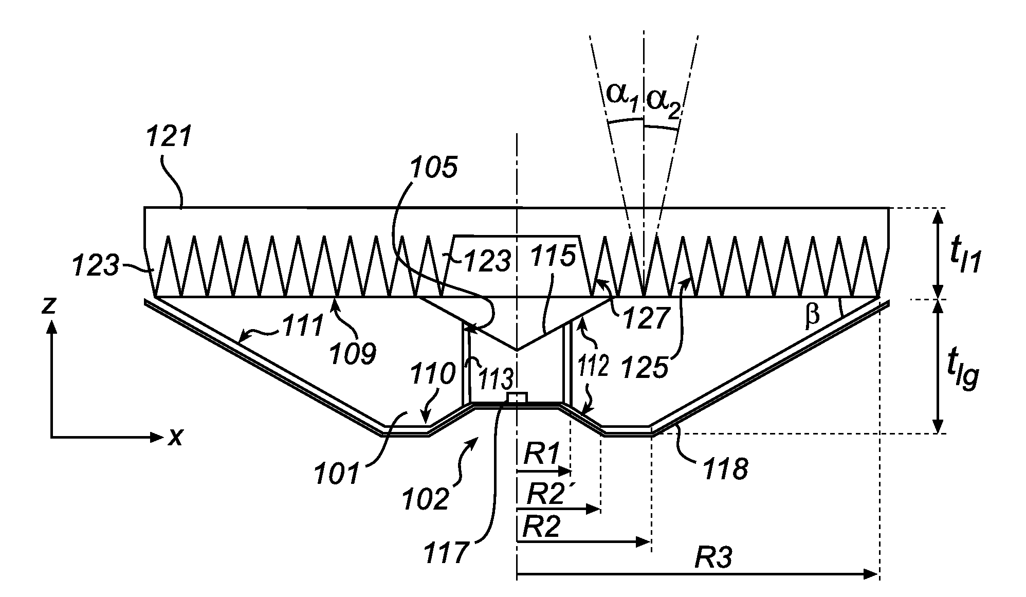
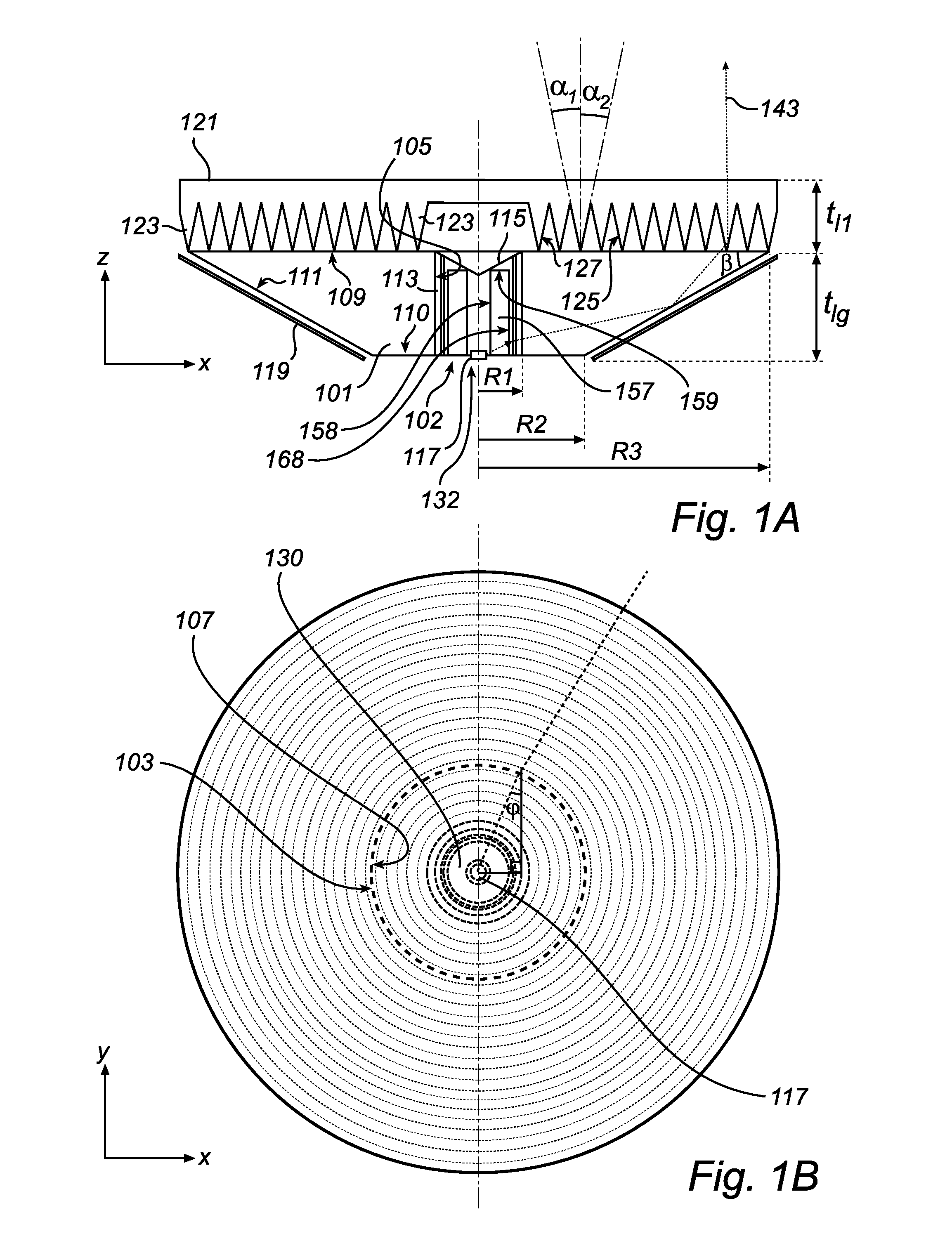
[0080]FIGS. 1a-1b show a cross-sectional side view and a top view of a luminaire arrangement according to a The shown luminaire arrangement comprises a light guide 101, here circle symmetric in a plane y-x. The light guide 101 has a cylindrical through-hole 102, which inner side is a light-entry surface 105 covered by a light emitting layer 113, here a layer that emits light upon illumination, preferably a phosphor layer. The light emitting layer 113 is not in direct contact with the light-entry surface 105, instead there is a small, equidistant air gap between the light-entry-surface 105 and the light emitting layer 113. The gap is preferably as small as possible without there being any optical contact between the surface 105 and the layer 113, preferably the gap is less than 1 mm. The layer 113 may even be in mechanical contact with the surface 103, as long as there is no optical contact. Note that in FIG. 1A the shown gap between the layer 113 and the surface 105 is exaggerated....

second embodiment

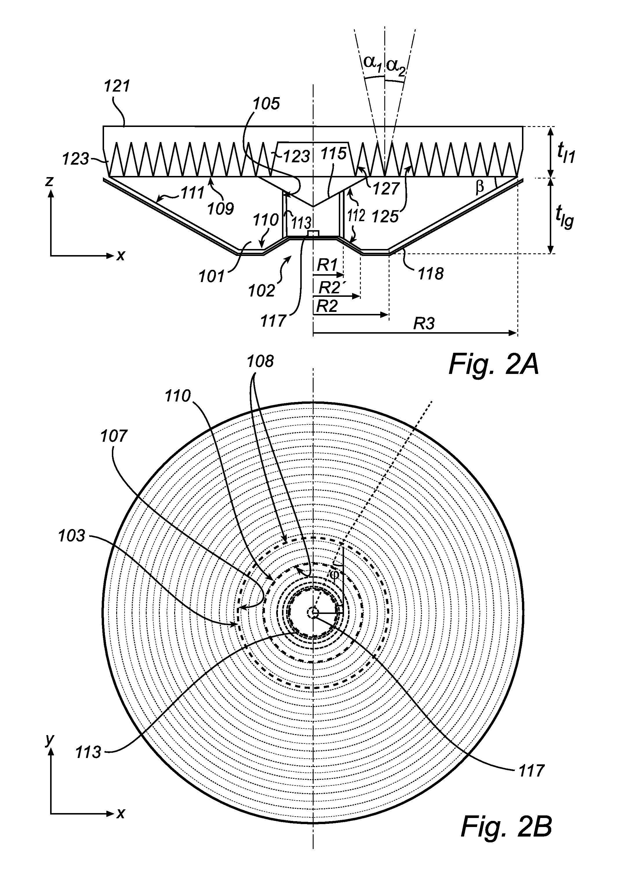
[0109]FIGS. 2a-2b show a cross-sectional side view and a top view of a luminaire arrangement according to a

[0110]Most is the same in the second embodiment and the first embodiment. However, one difference is that there is no second light guide 157 present and also that the mirror layer 119 has been replaced by a reflecting layer 118 covering not only the outer side of the reflecting surface 111 of the light guide, but also an outer surface side of the surfaces 110, 112 in the light-entry portion 103 and one opening of the cylindrical hole 102. However, it is understood that a second light guide may be used also with the second embodiment. Furthermore the light source 117 is in the second embodiment arranged on the side of the reflecting layer 118 facing the hole 102. The reflecting layer 118 has a mirror, or specularly reflecting, surface facing the light guide 101, and is preferably not in optical contact with the light guide 101.

[0111]Another difference between the embodiments of ...

third embodiment

[0144]Light can be coupled into the second light guide sections 175 via a light input cavity 167 comprising a light source 117b as shown in FIG. 5b, but can also, as an alternative or supplement, be coupled into second light guide sections 157 by a light source 117 (not shown in the embodiment of FIG. 5) arranged to illuminate a light input surface 158, typically a peripheral second light guide section 157 with a surface 158 that is not a closing surface, for example a light source 117 arranged opposite to such surface 158 as described above in connection with the

[0145]FIG. 6a-b show a respective 3-dimensional perspective view and side cross-sectional view of a luminaire arrangement according to a fifth embodiment. The optics for the output of light of this luminaire is more basic and straightforward than in the previous embodiments, but the principle of guiding light to a light emitting layer 113 using a second light guide 157 and cavities 174 is the same as in the fourth embodimen...


PUM


Abstract

An optical arrangement comprising a light guide (101) having a light-entry portion (103) with a light-entry surface (105), a tapering portion (107) with a light reflecting surface, and a light-exit surface (109). The light-entry portion (103) is arranged to guide light from the light-entry surface (105) in a first direction (x) towards the light reflecting surface (H I), the light reflecting surface being arranged in relation to the first direction (x) so that incident light from the light-entry portion (103) is reflected towards the light-exit surface (109). A light transmitting layer (113) is adapted to transmit light diffusively and arranged to cover at least a portion of the light-entry edge surface (105) of the light guide (101). The arrangement is e.g. suitable for use in a LED based luminaire and allows for efficiency and forming of a light beam able to fulfill glare requirements. The arrangement may advantageously be used in a downlighting application.

Description

FIELD OF THE INVENTION[0001]The present invention relates generally to an optical arrangement comprising a light transmitting layer adapted to transmit light diffusively.BACKGROUND OF THE INVENTION[0002]As the efficacy (lm / Watt) of light emitting diodes (LEDs) increases and prices go down, it is expected that LED illumination and LED based luminaires soon will be serious alternatives to and at a competitive level with hitherto predominant tube luminescent (TL) based luminaires.[0003]However, one issue with LED lighting is the provision of warm white light. All today available LEDs with high lumen efficacy (˜75 lm / Watt) produce light with a high color temperature (˜6000 K) and are perceived as cold white. For most general illumination applications a color temperature of 3000 K or less is preferred. In addition, the light should have a good color rendering index.[0004]Low color temperature with a good color rendering index can be accomplished by means of phosphor in combination with i...

Claims


Application Information

Patent Timeline
IPC IPC(8): F21V1/00F21V5/00
CPCG02B6/0021G02B6/003G02B6/0046G02B6/0028G02B6/0073G02B6/00G02B6/0055
Inventor IJZERMAN, WILLEM LUBERTUSVISSENBERG, MICHEL CORNELIS JOSEPHUS MARIEVAN DER TEMPEL, LEENDERTSABOU, FLORIAN COSMIN
Owner KONINKLIJKE PHILIPS ELECTRONICS NV
Why Eureka
Try Eureka