

Inductorless Isolated Power Converters With Zero Voltage and Zero Current Switching
a technology of isolated power converters and converters, applied in the direction of electric variable regulation, process and machine control, instruments, etc., can solve problems such as loss during switching, and achieve the effects of reducing induced voltage, reducing transformer leakage inductance, and increasing time delay
- Summary
- Abstract
- Description
- Claims
- Application Information
AI Technical Summary
Benefits of technology
Problems solved by technology
Method used
Image

Examples
Embodiment Construction
[0022]Example embodiments will now be described more fully with reference to the accompanying drawings.
[0023]Example embodiments are provided so that this disclosure will be thorough, and will fully convey the scope to those who are skilled in the art. Numerous specific details are set forth such as examples of specific components, devices, and methods, to provide a thorough understanding of embodiments of the present disclosure. It will be apparent to those skilled in the art that specific details need not be employed, that example embodiments may be embodied in many different forms and that neither should be construed to limit the scope of the disclosure. In some example embodiments, well-known processes, well-known device structures, and well-known technologies are not described in detail.
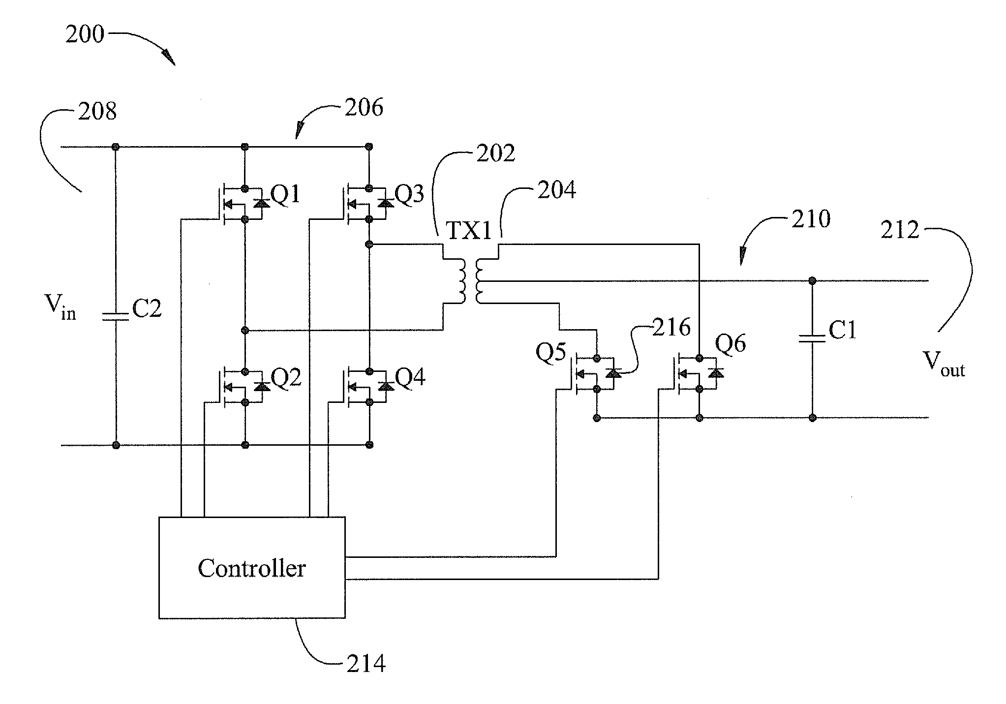
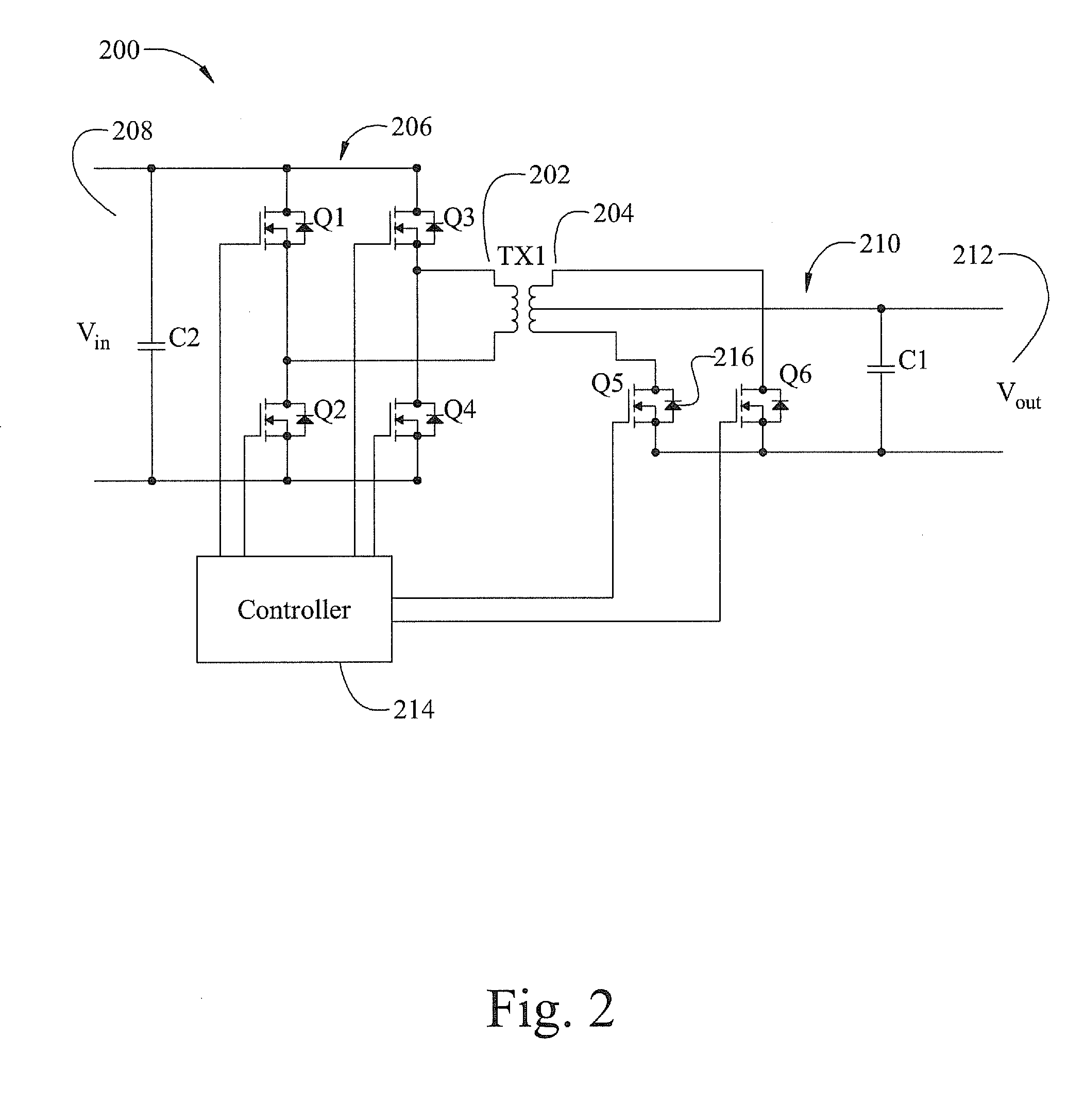
[0024]According to one aspect of the present disclosure an isolated switching power converter includes a transformer having a primary winding and a secondary winding, a primary side circuit coup...
PUM
 Abstract
Description
Claims
Application Information