
Discovery protocol

Inactive Publication Date: 2010-03-04
SNIF LABS
View PDF12 Cites 45 Cited by
  • Summary
  • Abstract
  • Description
  • Claims
  • Application Information

AI Technical Summary

Benefits of technology

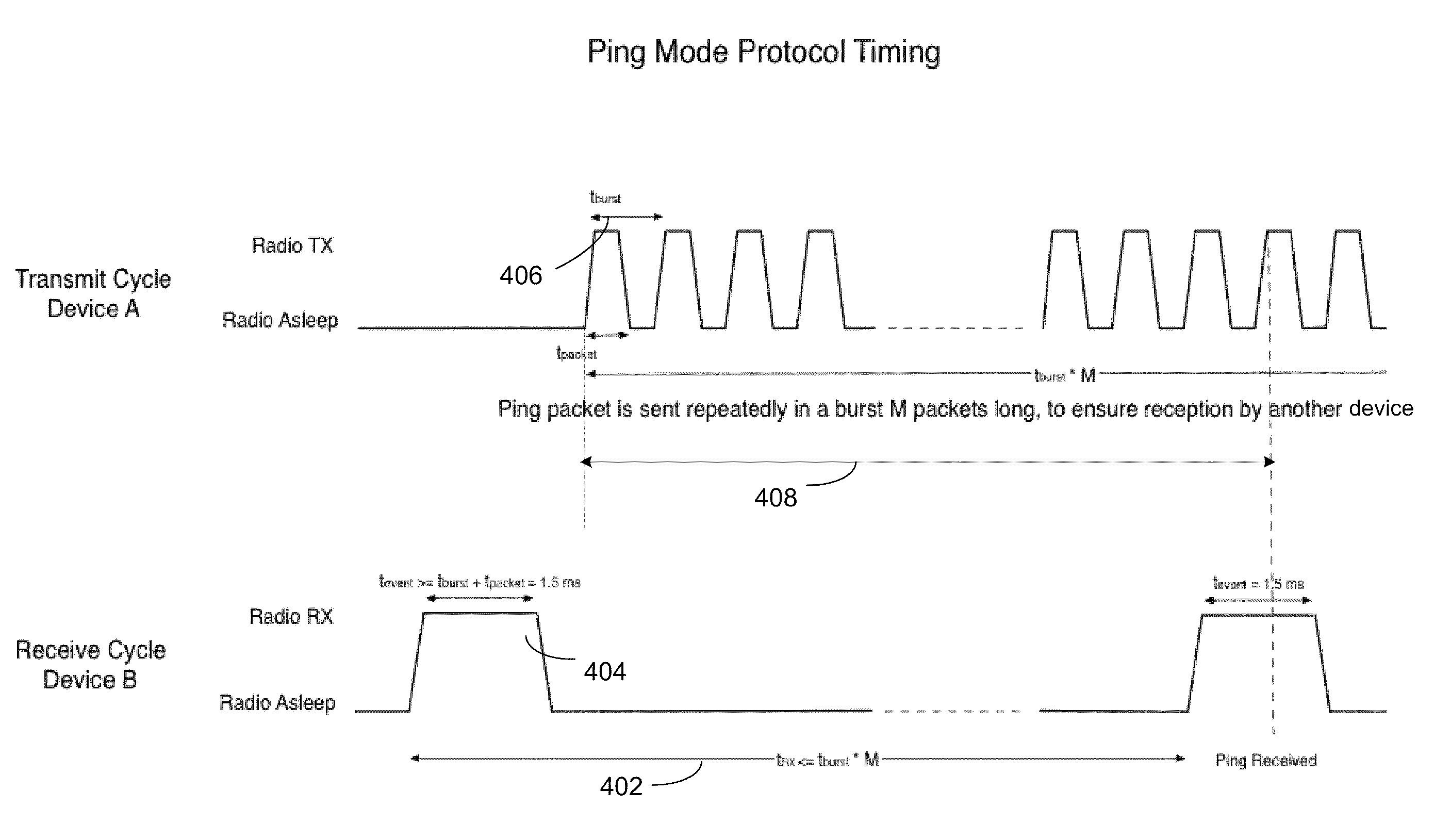
[0006]One or more of the following features may be included. At least one of the transmit ping, the live ping, and the new ping may comprise a plurality of packets, each transmitted at a burst interval. The burst interval may correspond to a time each packet in the plurality of packets is spaced apart. Further, at least one packet of the plurality of packets may be received in the transmit time. Moreover, the transmit time may be less than one burst interval. Furthermore, the detect duration may correspond to the transmit time plus one burst interval. Also, each packet may comprise at least one of a device identifier, status information, and a counter value.
[0007]In some embodiments, the transmit interval may be between about 3 seconds and about 12 seconds. Further, the burst interval may be between about 1 millisecond and about 2 milliseconds. Moreover, at least one of the transmit ping, the live ping, and the new ping may comprise between about 96 packets and about 320 packets. Additionally, the packets may be RF packets. The method may further comprise delaying, after receiving the live ping, transmission of a new ping for an additional backoff duration. The backoff duration may correspond to an amount of time configured to prevent pings from colliding.
[0008]In a second implementation, a method may comprise transmitting, via a transmitter, a plurality of transmit pings at a transmit interval. The transmit interval may correspond to a time between transmission of each transmit ping. Each transmit ping may include a number of packets. The method may further comprise listening, via a receiver, for a live ping, each live ping including a number of packets. The receiver may be configured to be turned on at a beginning of an assess interval, and off at an end of a detect duration. The assess interval may correspond to a time each packet

Problems solved by technology

Additionally, the method may comprise delaying, after receiving the live ping, transmission of a new ping for a delay duration.

Method used


Image

  • Discovery protocol
  • Discovery protocol
  • Discovery protocol

Examples


Embodiment Construction

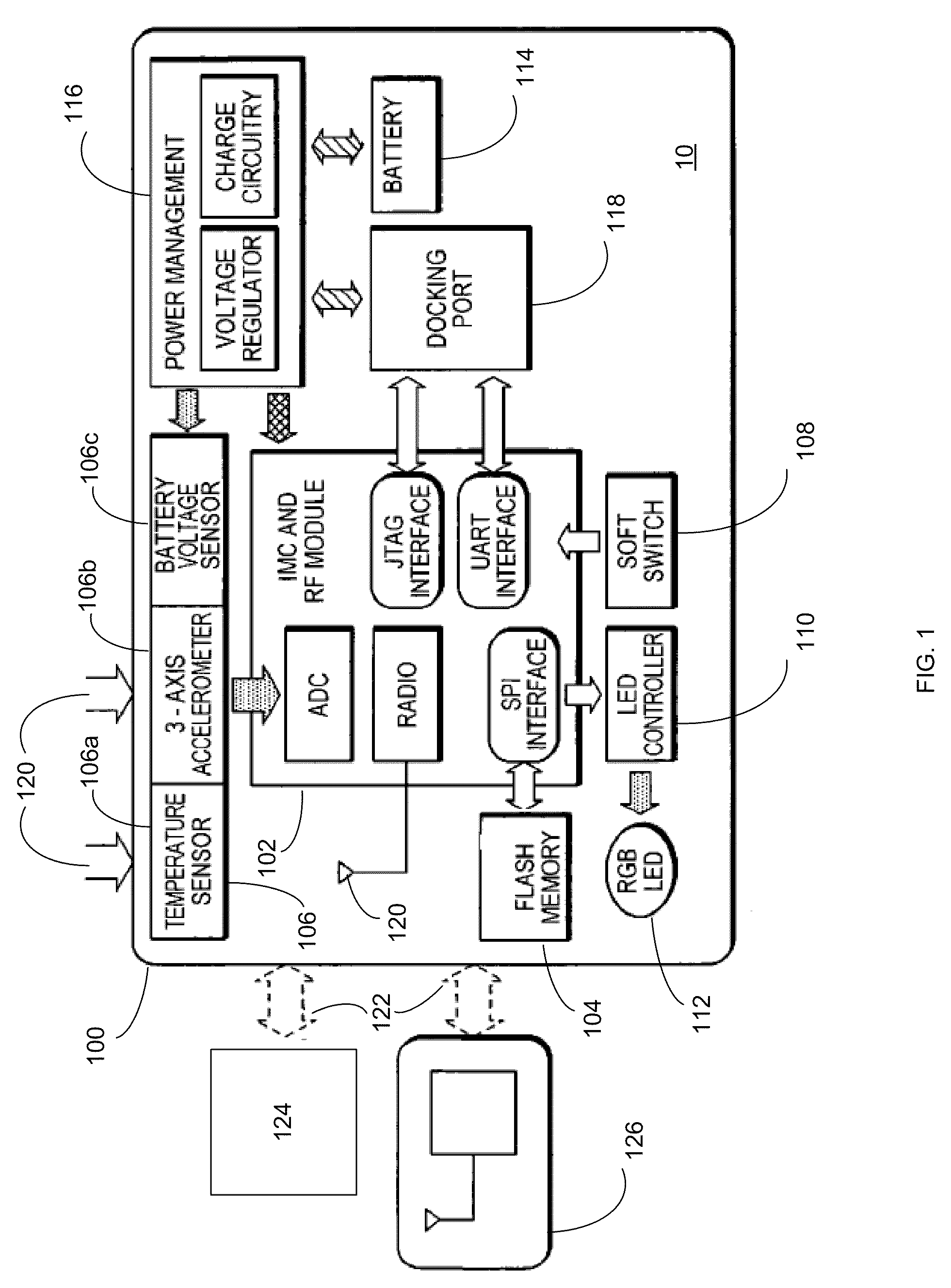
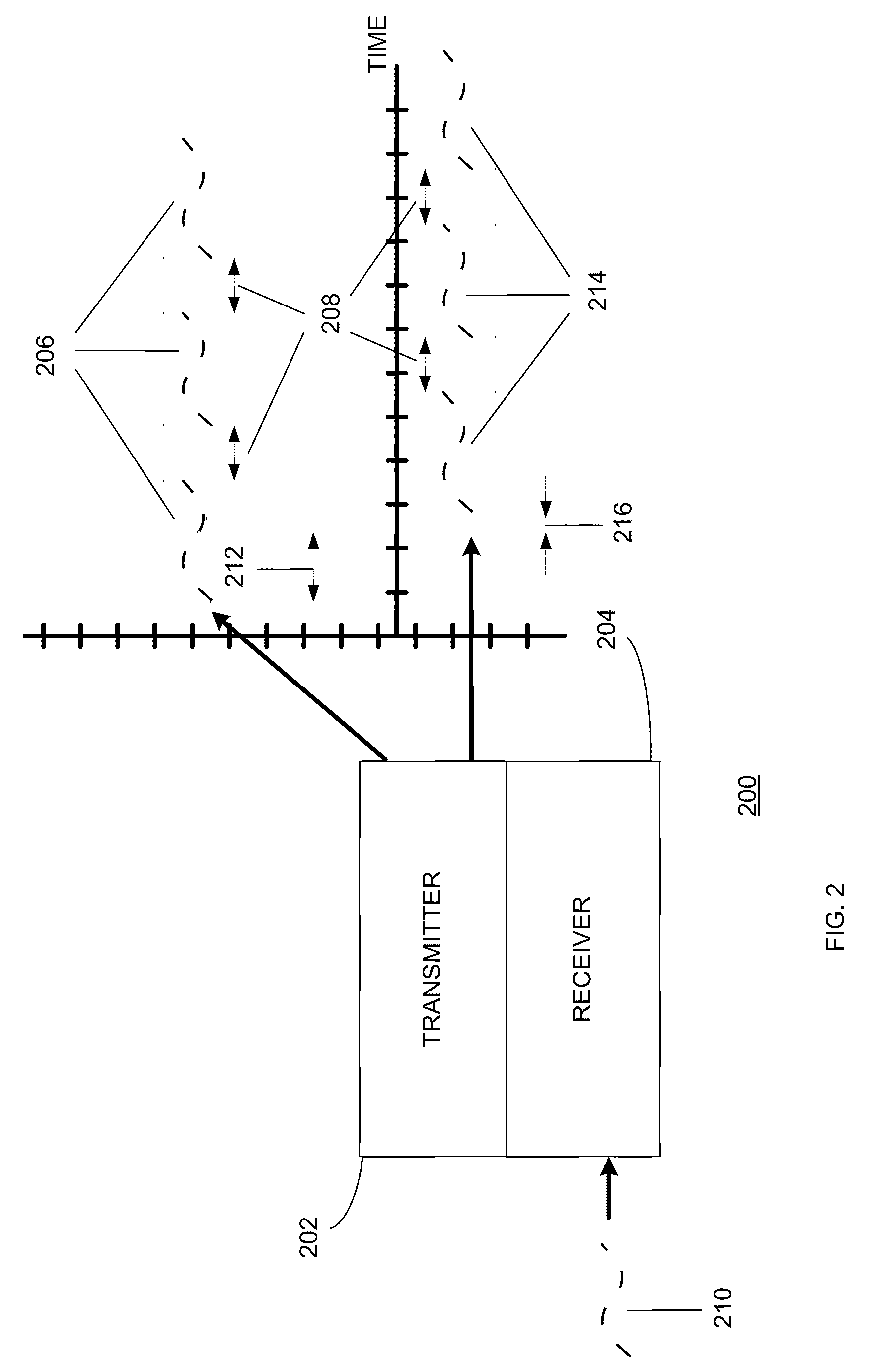
[0020]Referring to FIGS. 1 and 2, there is shown a monitoring system 10. Monitoring system 10 is merely an example of a system and / or device which may be configured to operate in accordance with the discovery protocol of the subject application. Monitoring system 10 may include RF module 102. Monitoring system 10 may be a monitoring device or electronic tag which may be attached to an object or worn by a person or animal. In one embodiment, as shown in FIG. 2, an RF module (e.g., RF module 200) may include transmitter 202 and receiver 204. Monitoring system 10 may comprise several components housed in an enclosure 100. Enclosure 100 may be of a compact form that may be attached to an object. For example, enclosure 100 may be worn by an animal such as a dog. The enclosure 100 may be fixed to a collar or other device. In such a case, enclosure 100 may take the form of a conventional tag, such as a dog tag, or an ID tag worn by an employee at a workplace, such as a hospital. Monitoring...


PUM


Abstract

A method and device may comprise transmitting, via a transmitter, a plurality of transmit pings at a transmit interval. A receiver may listen, for a live ping and the receiver may be configured to be turned on at a beginning of the assess interval, and off at an end of the detect duration. The receiver may further receive the live ping. After receiving the live ping, transmission of a new ping may be delayed for a delay duration. The new pings may be transmitted at the transmit interval.

Description

RELATED APPLICATIONS[0001]This application claims the benefit of U.S. Provisional Patent Application No. 61 / 093,909 filed on 3 Sep. 2008, the entire contents of which are herein incorporated by reference.BACKGROUND OF THE INVENTION[0002]This disclosure relates to a discovery protocol and, more particularly, to a system and method for discovering devices.[0003]Some devices, such as wireless sensors including active radio frequency identification (RFID) tags may be capable of discovering other devices. To receive signals and, in turn, discover devices which may have sent those signals, the devices may need to have a receiver that may be powered on and off. Further, in order to be discovered by other devices, these same devices may need to transmit one or more signals.[0004]Additionally, while transmitting and receiving signals, these devices may require additional power. The device's receiver may be continuously powered on for a relatively long time before a signal is received, and in...

Claims


Application Information

Patent Timeline
IPC IPC(8): H04L12/26
CPCH04L12/2697H04L41/12H04W52/0229H04W8/005H04L67/12H04L43/50Y02D30/70
Inventor GIPS, JONATHANAYLWARD, RYANLAIBOWITZ, MATHEW
Owner SNIF LABS
Learn More