Method of transferring timing information over packet network

a technology of timing information and packet network, applied in the direction of time-division multiplex, multiplex communication, electrical apparatus, etc., can solve the problem of considerable time, and achieve the effect of robustness and accurate solution

Active Publication Date: 2010-03-04
QUALCOMM INC +1
View PDF9 Cites 11 Cited by
  • Summary
  • Abstract
  • Description
  • Claims
  • Application Information

AI Technical Summary

Benefits of technology

[0008]The novel method in accordance with the invention allows the local clock to track the reference clock through unknown network with minimum error. The Least Square method is an effective solution for a general unknown network delay distribution as it is very robust and accurate

Problems solved by technology

In order to provide an accurate update of the receiver DCO, a large amount of data needs to be collected, and at a low transmission rate, this can take considerable time.

Method used


Image

  • Method of transferring timing information over packet network
  • Method of transferring timing information over packet network
  • Method of transferring timing information over packet network

Examples


Embodiment Construction

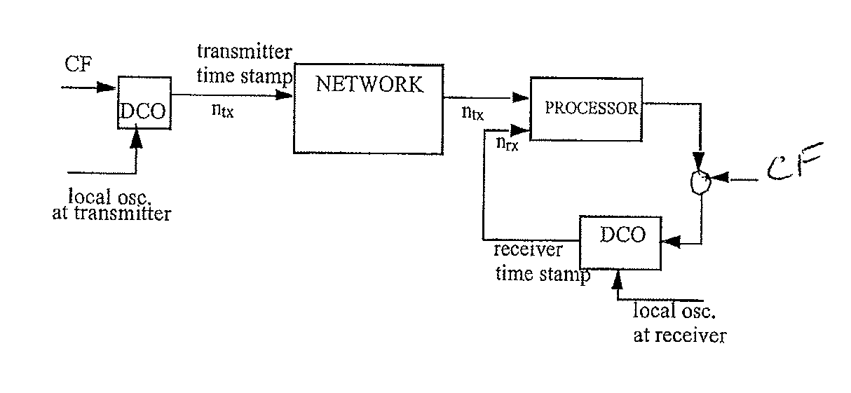
[0017]The general expression for the time stamps can be expressed as:

ntx=k·T·ftx,

nrx=(k·T+Δk)·frx+Φ

where ntx and nrx are time stamps of packet at transmitter and receiver side respectively, with ftx and frx as the respective DCO frequencies. T is the time interval between two consecutive timing packets and k is the index. If Δk is the network delay and Φ is the initial phase offset between the transmitter DCO and the receiver DCO, the transit time is the difference between ntx and nrx.

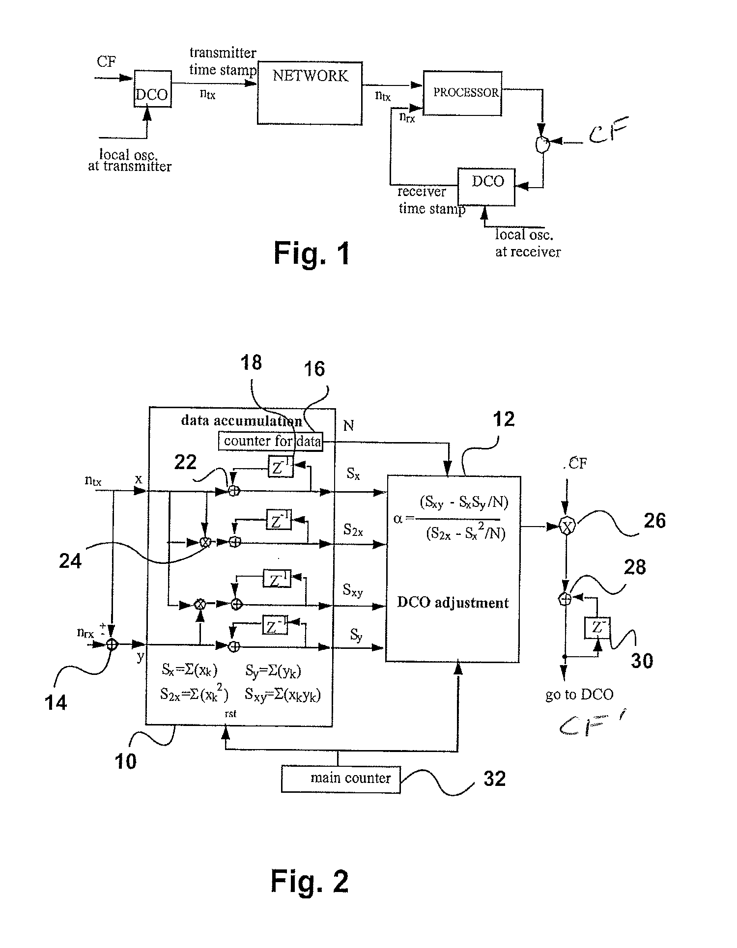
[0018]This transit time can be expressed as:

ntxnrx=k·T·(ftx−frx)+Δk·frx+Φ

where yk=ntx−nrx is the transit time,

α=1-frxftx

is the frequency deviation of interest, (106·α is the deviation of the local clock in ppm), xk=k·T·ftx is the transmitter timestamp, and vk=Δk·frx+Φ is the noise containing the network delay as the noise source. Since ftx remains relatively constant with only a small change during a DCO update, vk mostly represents the network delay variation with a phase offset. The estimate can now ...


PUM


Abstract

Timing information is transmitted over a network by sending time-stamped packets between a transmitter and receiver. The time-stamped packets are used to compute an estimate of the frequency deviation between the transmitter clock and the receiver clock. The local receiver clock is periodically updated to match the transmitter clock based on the estimate, which is preferably a least squares estimate. A multiple window approach is employed to increase update speed.

Description

FIELD OF THE INVENTION[0001]This invention relates to the transfer of timing information over packet networks, and more particularly to a method wherein timestamps are sent from the transmitter to the receiver to enable synchronization of the receiver.BACKGROUND OF THE INVENTION[0002]In order to send time sensitive information, such as voice and video data, over asynchronous networks, some means must be employed or transferring timing information between the transmitting and receiving end. Timing-over-Packet (ToP) technology enables accurate timing and synchronization to be distributed across asynchronous packet infrastructures, allowing carriers to confidently support time-critical services over packet networks.[0003]A network including ToP technology is shown in FIG. 1. The transmitter side includes a digital controlled oscillator (DCO) referenced to a local oscillator at the transmitter. The center frequency (CF) of the DCO at the transmitter side is set by a digital word. The ou...

Claims


Application Information

Patent Timeline
Patent Type & Authority Applications(United States)
IPC IPC(8): H04J3/06
CPCH04J3/0664
Inventor JIN, GARY
Owner QUALCOMM INC
Why Eureka
Try Eureka