
Multilevel Cluster-based MIMO Detection Method and MIMO Detector Thereof

a detection method and cluster technology, applied in the field of wireless communication system, can solve the problems of reducing reducing the efficiency of the system, and not enhancing the noise of both methods, so as to reduce the complexity of the mimo system

Active Publication Date: 2010-03-04
REALTEK SEMICON CORP
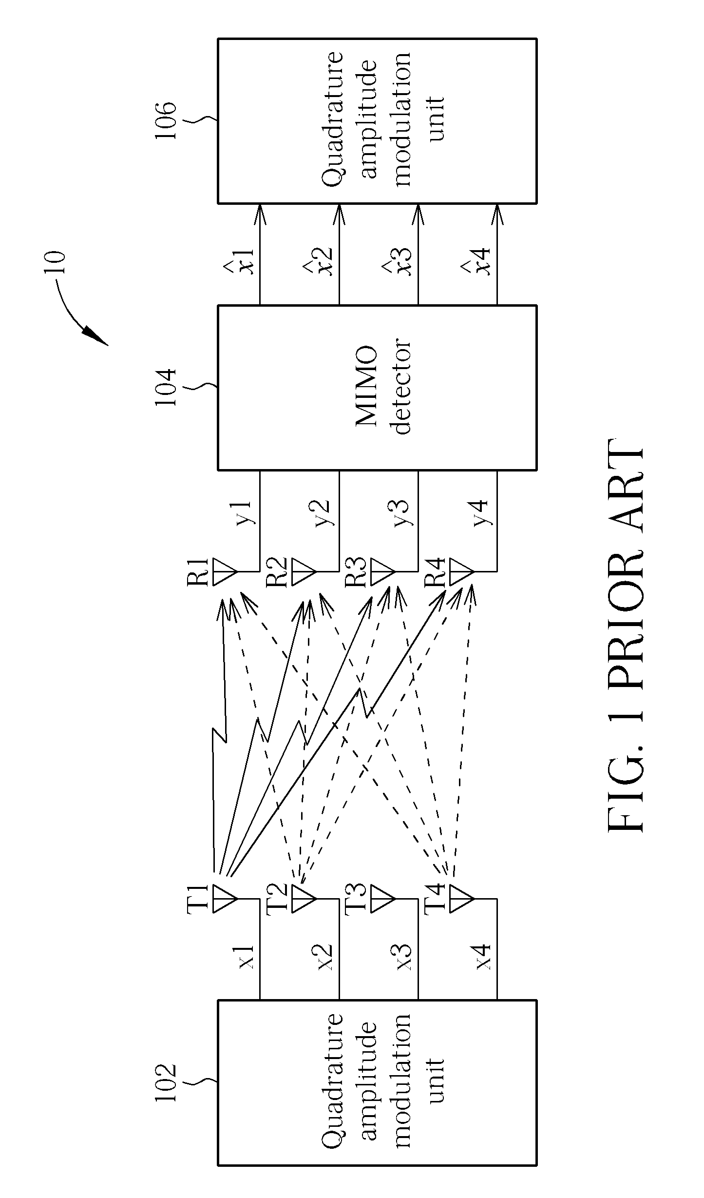
View PDF2 Cites 29 Cited by
  • Summary
  • Abstract
  • Description
  • Claims
  • Application Information

AI Technical Summary

Benefits of technology

[0016]Therefore, the present invention provides a MIMO detection method utilized in a receiver of a MIMO system and related MIMO detector, for reducing the complexity of the MIMO system.

Problems solved by technology

On the other hand, MMSE algorithm cannot remove ISI completely, but does not enhance noise.
Both methods are simple to be implemented, but have limited efficiency In addition, nonlinear MIMO detection method includes vertical bell laboratories layered space time (V-BLAST) algorithm, maximum likelihood (ML) algorithm, sphere decoding (SD) algorithm, etc.
ML algorithm has the best performance, but has the most complexity of all the algorithms.
However, a channel effect affects a process of determining a search radius of SD algorithm under the condition of low signal-to-noise ratio (SNR), and increases the complexity.
The method published in “Depth-First and Breadth-First Search Based Multilevel SGA Algorithms for Near Optimal Symbol Detection in MIMO Systems” provides depth-first search or breadth-first search to extract possible transmitted signals by sequential Gaussian approximation (SGA) algorithm which uses ZF algorithm, causing performance degradation.
However, the method disclosed by the U.S. Pat. No. 7,308,047 causes serious system error and error floor effect at low bit error rate (BER).
Although the abovementioned multilevel structure of the QAM technology for detecting transmitted signal can reduce the system complexity, a problem of system error is still needed to conquer, for enhance accuracy of the MIMO detection.

Method used


Image

  • Multilevel Cluster-based MIMO Detection Method and MIMO Detector Thereof
  • Multilevel Cluster-based MIMO Detection Method and MIMO Detector Thereof
  • Multilevel Cluster-based MIMO Detection Method and MIMO Detector Thereof

Examples


Embodiment Construction

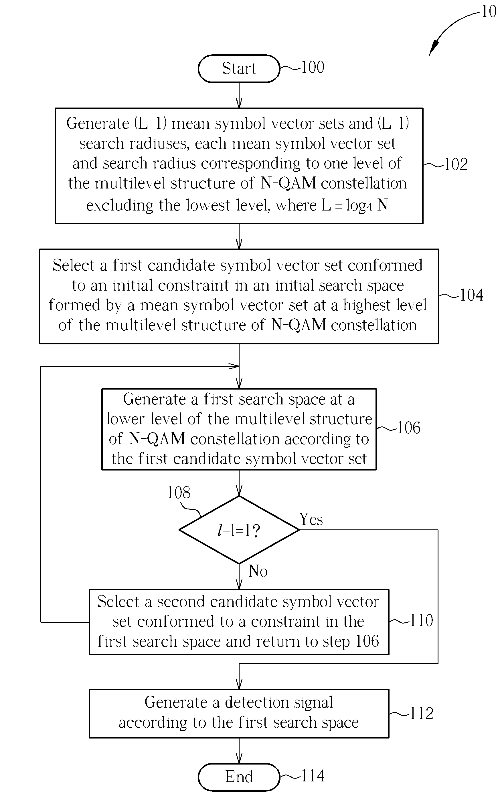
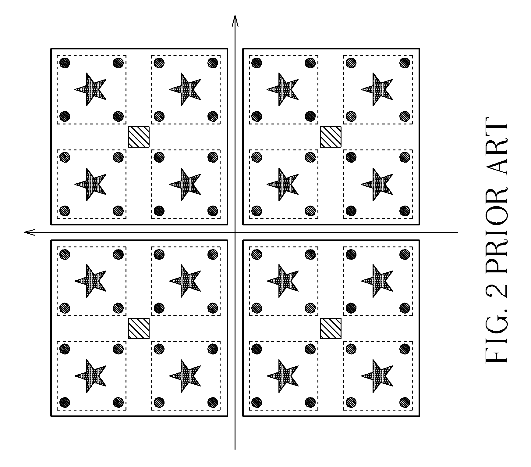
[0027]As abovementioned, N-QAM constellation has a characteristic of a multilevel structure, and thereby the present invention discloses a MIMO detection method which performs two-stage search in a received signal space. The first stage is called “cluster matching” which is a breadth-first search, and the second stage is called “detail matching”. Cluster matching begins at the highest level (namely the Lth level, where L=log4 N) of the multilevel structure of N-QAM constellation. A mean symbol vector set XL at the Lth level is considered as an initial search space, and cluster matching is performed for each of (L−1) levels for reducing the search space, so as to find a cluster whose symbol vectors have minimal distances with the transmitted signal. Detail matching is performed at the lowest level of the multilevel structure of N-QAM constellation, namely the first level (which is also the lowest level), to find a symbol vector which has a minimal distance with the transmitted signal...


PUM


Abstract

A MIMO detection method for a receiver in a MIMO system using N-QAM for modulation, the MIMO detection method including generating a plurality of symbol vector sets and a plurality of search radiuses, selecting a candidate symbol vector set corresponding to a highest level of a multilevel structure of N-QAM constellation, generating a search space corresponding to a lower level of the multilevel structure of N-QAM constellation according to the selected candidate symbol vector set, confirming which level the search space corresponds to, and generating a detection signal according to the search space when the level of the search space is the lowest level of the multilevel structure of the N-QAM constellation.

Description

CROSS REFERENCE TO RELATED APPLICATIONS[0001]This application claims the benefit of U.S. Provisional Application No. 61 / 093,355, filed on Aug. 31, 2008 and entitled “Multilevel Cluster-Based MIMO Detection”, the contents of which are incorporated herein.BACKGROUND OF THE INVENTION[0002]1. Field of the Invention[0003]The present invention relates to a wireless communication system, and more particularly, to MIMO communication system.[0004]2. Description of the Prior Art[0005]Multiple-Input Multiple-Output (MIMO) technology utilizes antenna array to receive and transmit signals, which increases channel capacity with present spectrum resource, prevents signal loss caused by multiple-path, and meanwhile increases communication coverage. The present wireless communication standards, such as IEEE 802.11n used by wireless local area network, IEEE 802.16 used by WiMax, and long term evolution (LTE) initiated by the 3rd Generation Partnership Project (3GPP) all utilize MIMO technology to inc...

Claims


Application Information

Patent Timeline
Patent Type & Authority Applications(United States)
IPC IPC(8): H03D1/24H03D1/00
CPCH04L27/34H04L25/03242
Inventor CHENG, SHAU-YULEE, CHENG-YUANLAI, WEI-CHIHSU, TERNG-YIN
Owner REALTEK SEMICON CORP
Learn More