Steam generator of steam oven
- Summary
- Abstract
- Description
- Claims
- Application Information
AI Technical Summary
Benefits of technology
Problems solved by technology
Method used
Image
Examples
first embodiment
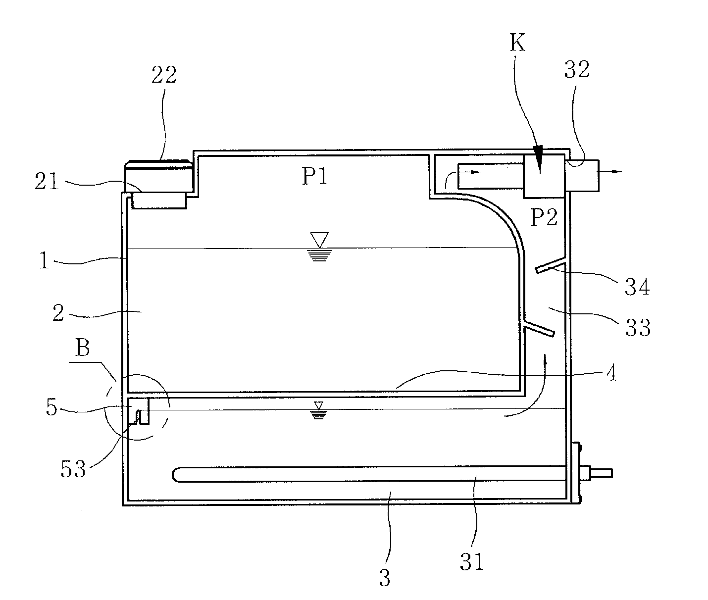
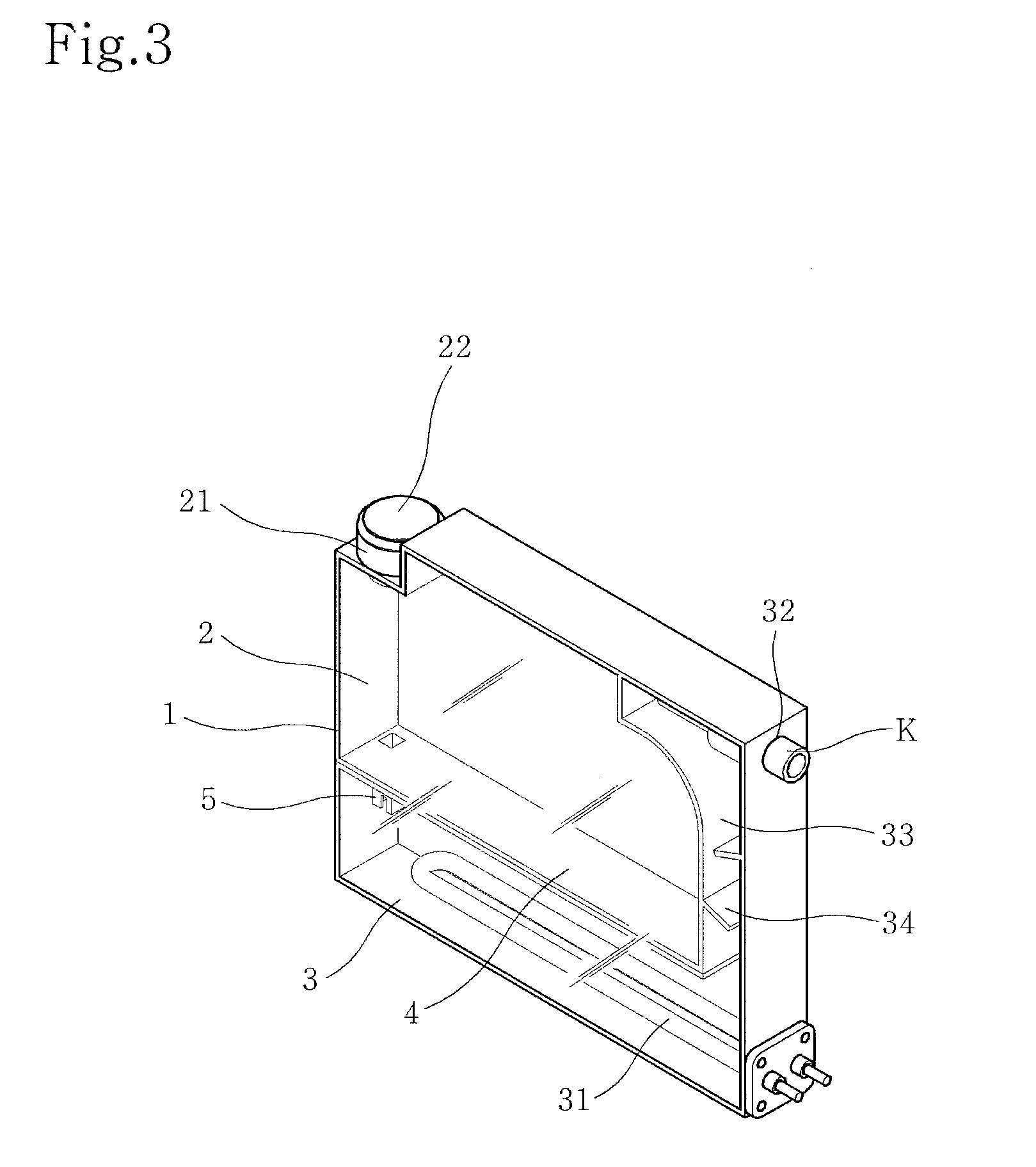
[0035]FIGS. 3 to 10 illustrate a steam generator according to the present invention. More particularly, FIG. 3 is a perspective view illustrating the overall configuration of the steam generator, FIG. 4 is a longitudinal sectional view of FIG. 3, and FIG. 5 is an enlarged sectional view of the portion “B” in FIG. 4.
[0036]As shown, the steam generator according to the present invention includes a rectangular upright body 1 having a water pouring hole 21 and a steam discharge hole 32. The inner space of the upright body 1 is divided into upper and lower compartments by a partition 4, the upper compartment serving as a water supply compartment 2 and the lower compartment serving as a boiler compartment 3. A water supply passage 5 is provided between the water supply compartment 2 and the boiler compartment 3, to allow water stored in the water supply compartment 2 to be introduced into the boiler compartment 3 through the water supply passage 5.
[0037]The water pouring hole 21 and the s...
second embodiment
[0060]FIGS. 11 and 12 illustrate a steam generator according to the present invention. More particularly, FIG. 11 is a perspective view illustrating the overall configuration of the steam generator, and FIG. 12 is a longitudinal sectional view of FIG. 11.
[0061]The most important difference between the present embodiment and the previously described first embodiment is positions of the water pouring hole 21 provided with the plug 22 and the steam discharge hole 32.
[0062]Differently from the first embodiment of the present invention in which the water pouring hole 21 is located at the opposite side of the steam discharge hole 32, in the second embodiment of the present invention, the water pouring hole 21 is located at the same side as the steam discharge hole 32. When providing the water pouring hole 21 at the opposite side of the steam discharge hole 32, water can be supplemented through the water pouring hole 21 without completely separating the upright body 1 of the steam generato...
third embodiment
[0065]FIGS. 13 to 15 illustrate a steam generator according to the present invention. More particularly, FIG. 13 is a perspective view illustrating the overall configuration of the steam generator, FIG. 14 is a longitudinal sectional view of FIG. 13, and FIG. 15 is a perspective view illustrating the steam generator installed on the top of the cabinet.
[0066]The present embodiment, as shown in FIG. 15, has a feature in that the steam generator is mounted on the top of the cabinet 110. In this case, the body of the steam generator is configured to be laid horizontally on the cabinet so as not to require a wide installation area therefor. In this case, the fixing bracket 8 is mounted on the top of the cabinet 110 to support and fix the body of the steam generator.
[0067]Similar to the above described first and second embodiments of the present invention, the technical principal of Torricelli's Experiment also can be applied to the steam generator according to the third embodiment of the...
PUM
| Property | Measurement | Unit |
|---|---|---|
| Pressure | aaaaa | aaaaa |
| Width | aaaaa | aaaaa |
Abstract
Description
Claims
Application Information
 - R&D
- Intellectual Property
- Life Sciences
- Materials
- Tech Scout
- Unparalleled Data Quality
- Higher Quality Content
- 60% Fewer Hallucinations
Browse by: Latest US Patents, China's latest patents, Technical Efficacy Thesaurus, Application Domain, Technology Topic, Popular Technical Reports.
© 2025 PatSnap. All rights reserved.Legal|Privacy policy|Modern Slavery Act Transparency Statement|Sitemap|About US| Contact US: help@patsnap.com


