Load lock chamber for large area substrate processing system

a processing system and large area technology, applied in the direction of thin material processing, article separation, electrical equipment, etc., can solve the problems of affecting the vacuum level between the transfer chamber and the factory interface, and achieve the effect of reducing the contamination of substrates

Active Publication Date: 2010-03-04
APPLIED MATERIALS INC
View PDF12 Cites 15 Cited by
  • Summary
  • Abstract
  • Description
  • Claims
  • Application Information

AI Technical Summary

Benefits of technology

[0009]The present invention generally includes a load lock chamber for transferring large area substrates into a vacuum processing chamber. The load lock chamber may have one or more separate, environmentally isolated environments. Each processing environment may have a plurality of exhaust ports for drawing a vacuum. The exhaust ports may be located at the corners of the processing environment. W

Problems solved by technology

Thus, there may be an abrupt change in vacuum level b

Method used


Image

  • Load lock chamber for large area substrate processing system
  • Load lock chamber for large area substrate processing system
  • Load lock chamber for large area substrate processing system

Examples


Embodiment Construction

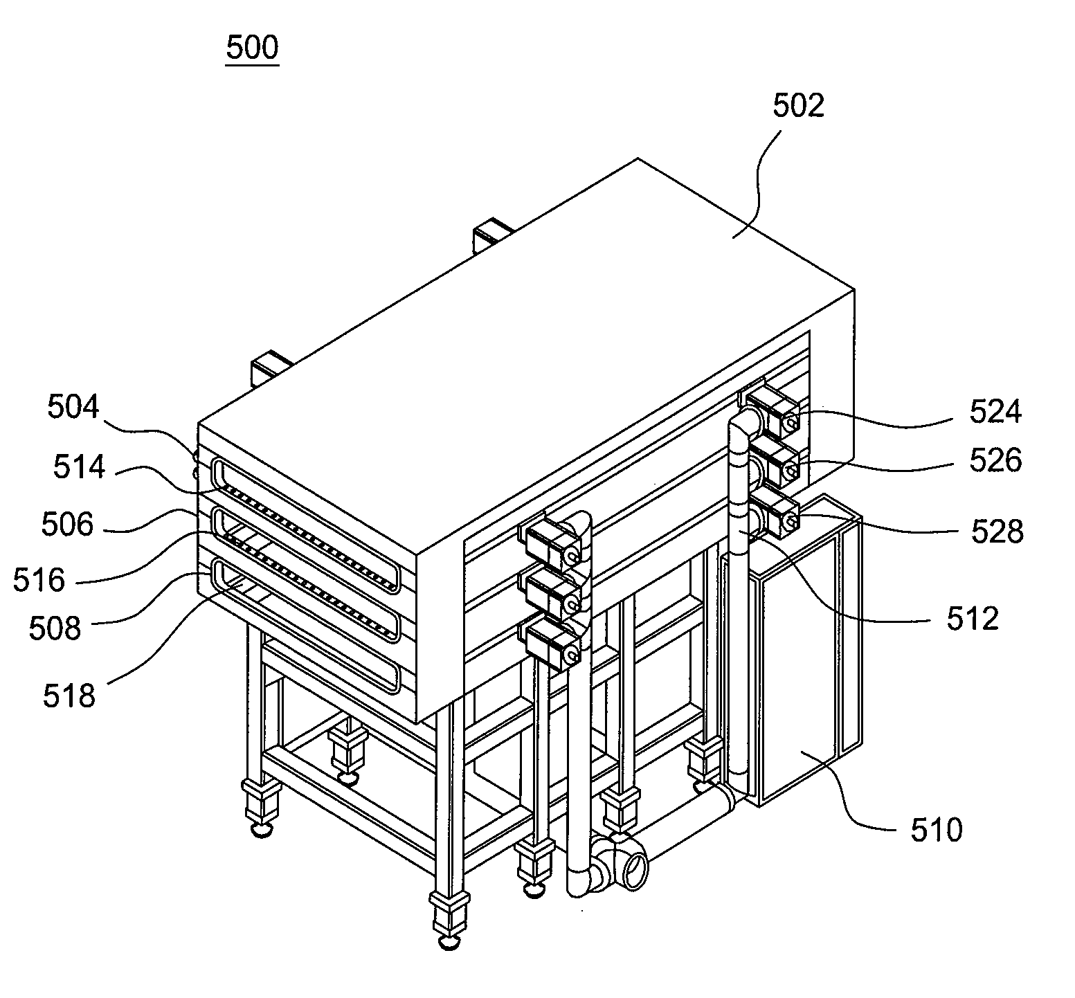
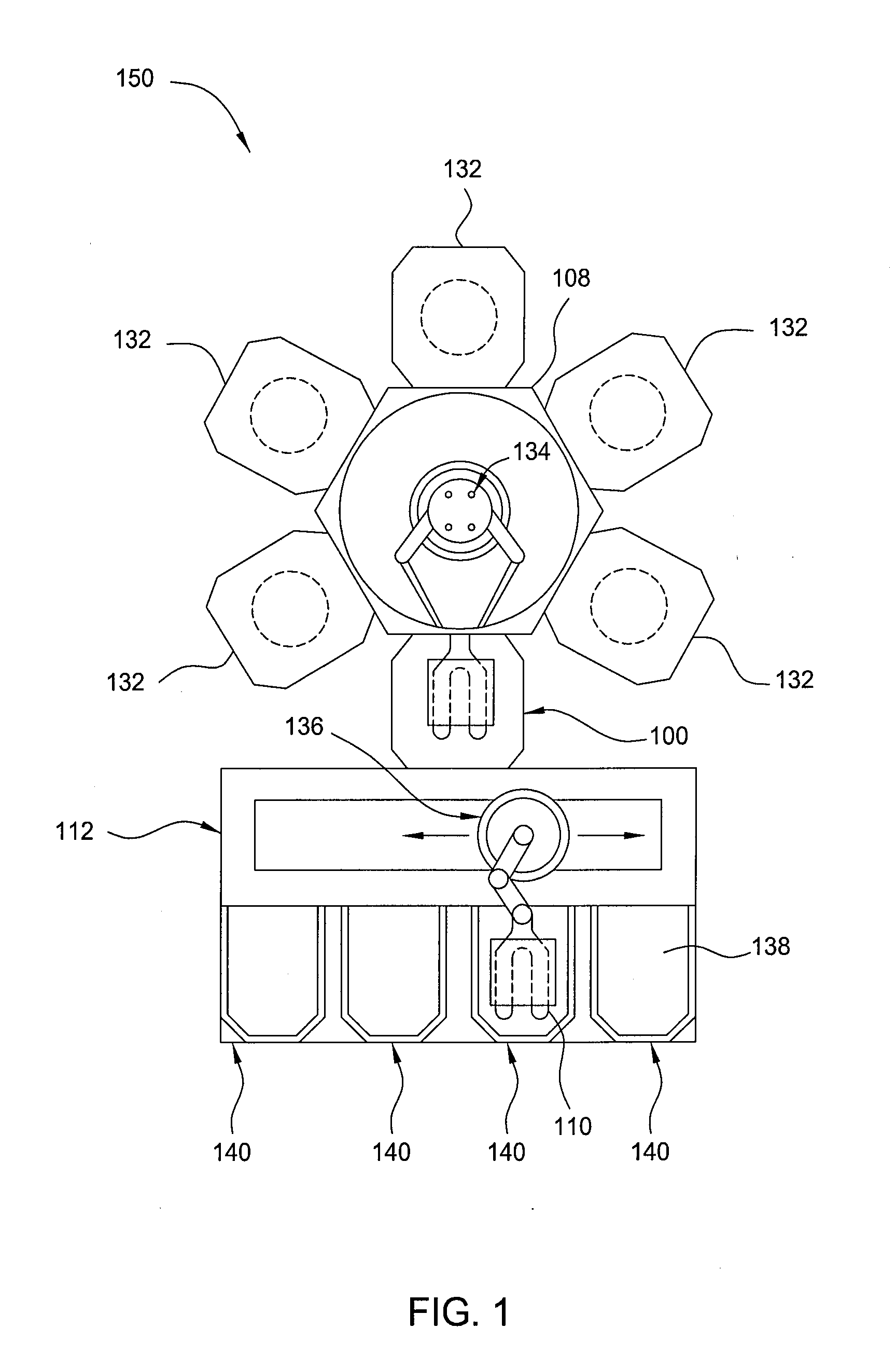
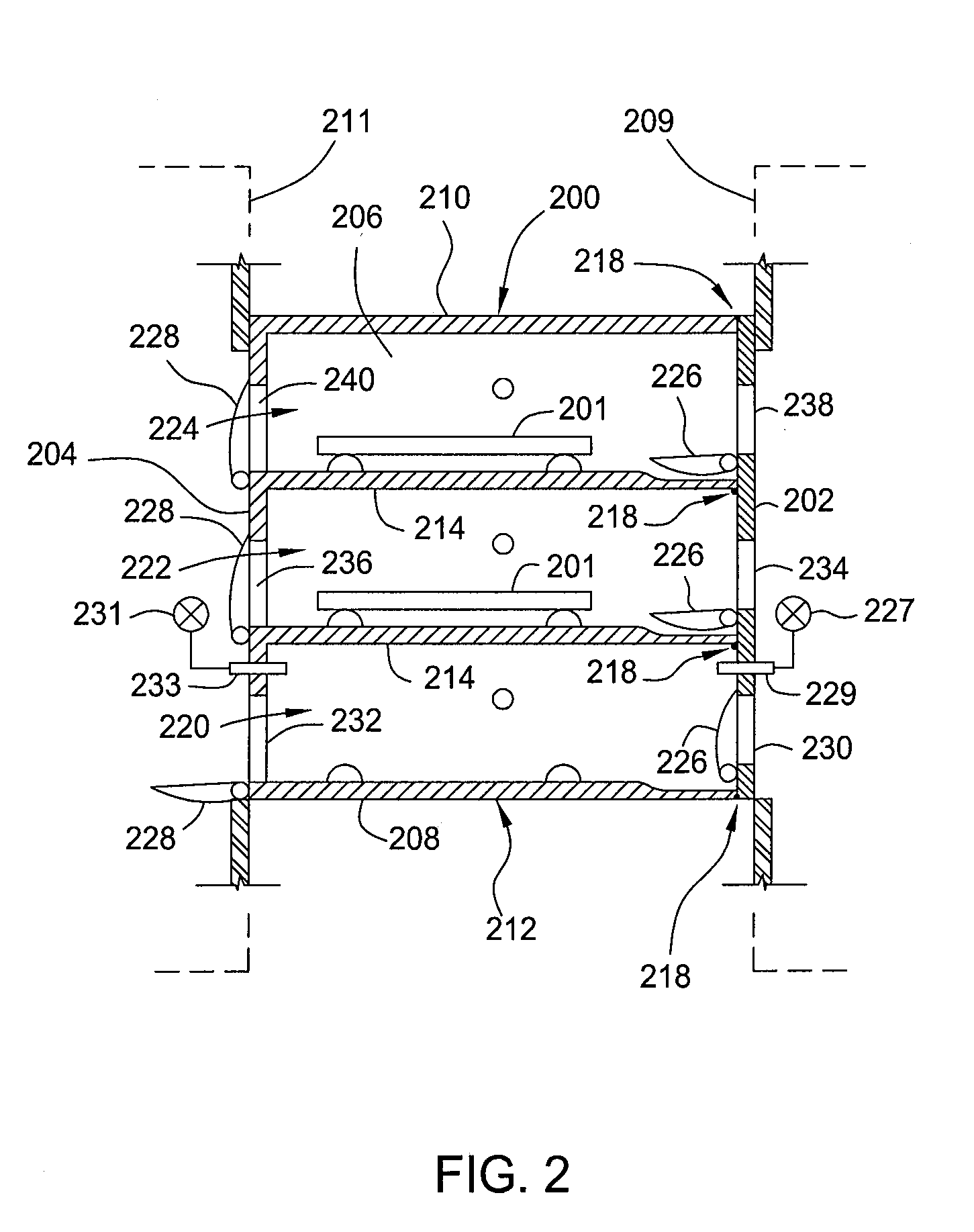
[0022]The present invention generally includes a load lock chamber for transferring large area substrates into a vacuum processing chamber. The load lock chamber may have one or more separate, environmentally isolated environments. Each processing environment may have a plurality of exhaust ports for drawing a vacuum. The exhaust ports may be located at the corners of the processing environment. When a substrate is inserted into the load lock chamber from a factory interface, the environment may need to be evacuated. Due to the exhaust ports located at the corners of the environment, any particles or contaminants that may be present may be pulled to the closest corner and out of the load lock chamber without being pulled across the substrate. Thus, substrate contamination may be reduced.

[0023]The invention is illustratively described below in regards to a load lock chamber, such as those available from AKT America, Inc., a subsidiary of Applied Materials, Inc., Santa Clara, Calif. H...


PUM


Abstract

The present invention generally includes a load lock chamber for transferring large area substrates into a vacuum processing chamber. The load lock chamber may have one or more separate, environmentally isolated environments. Each processing environment may have a plurality exhaust ports for drawing a vacuum. The exhaust ports may be located at the corners of the processing environment. When a substrate is inserted into the load lock chamber from the factory interface, the environment may need to be evacuated. Due to the exhaust ports located at the corners of the environment, any particles or contaminants that may be present may be pulled to the closest corner and out of the load lock chamber without being pulled across the substrate. Thus, substrate contamination may be reduced.

Description

BACKGROUND OF THE INVENTION[0001]1. Field of the Invention[0002]Embodiments of the invention generally relate to a load lock chamber for transferring large area substrates into a vacuum processing environment.[0003]2. Description of the Related Art[0004]When processing substrates to manufacture flat panel displays, organic light emitting displays (OLEDs), solar panels, and semiconductors, multiple processes may be performed in order to achieve the desired end product. Some of the processes may be performed under vacuum. Examples of vacuum processes that may be used include plasma enhanced chemical vapor deposition (PECVD), physical vapor deposition (PVD), etching, and others.[0005]When multiple vacuum processes are performed, it may be beneficial to have the different chambers coupled to a common transfer chamber. By coupling a plurality of processing chambers to a common vacuum chamber, the substrate may have a first process performed on it in a first chamber. Thereafter, the subst...

Claims


Application Information

Patent Timeline
IPC IPC(8): H01L21/677
CPCH01L21/67236H01L21/67201H01L21/02H01L21/68
Inventor BEHDJAT, MEHRANKURITA, SHINICHIINAGAWA, MAKOTOANWAR, SUHAIL
Owner APPLIED MATERIALS INC
Why Eureka
Try Eureka