Bearing structure, motor, and fan apparatus

a technology of bearing structure and rotating shaft, which is applied in the direction of positive displacement liquid engine, piston pump, liquid fuel engine, etc., can solve the problems of swaying of the rotating shaft, failure to support the rotating shaft stably, and insufficient positioning of the sleeve and the rotating shaft, so as to achieve easy optimization of the amount of pressing force and reduce the effect of pressing for

Active Publication Date: 2010-03-04
NIDEC CORP
View PDF7 Cites 18 Cited by
  • Summary
  • Abstract
  • Description
  • Claims
  • Application Information

AI Technical Summary

Benefits of technology

[0010]In bearing structures according to preferred embodiments of the present invention, a plurality of ribs including the contact surface arranged to make contact with at least a portion of the outer surface of the sleeve are provided on the inner surface of the cavity portion of the sleeve support portion, and the ribs are preferably defined by a plurality of types of ribs, each type of the ribs being different in the axial position of the axial edge of the contact surface on the axially opening portion side. Despite their simple structure the number of ribs that make contact with the sleeve can be reduced to easily optimize the amount of pressing force applied by the ribs onto the sleeve for that portion of the sleeve which is located toward the axially opening portion side so that an appropriate reduction in the pressing force can be achieved to reduce deformation of the sleeve (e.g., to prevent an excessive reduction in inside diameter of the sleeve). A greater number of ribs are arranged to make contact with a remaining portion of the sleeve which is located on the opposite side to the axially opening portion side, as compared to the number of ribs arranged to make contact with that portion of the sleeve which is located toward the axially opening portion side. This contributes to pressing the sleeve securely so as to ensure stable support of the sleeve, while reducing the deformation of the sleeve caused by circumferential variations in the pressing force applied by the ribs onto the sleeve.

Problems solved by technology

For example, when the pressing force applied by the ribs of the sleeve support portion onto the sleeve is too small, the positioning of the sleeve and the rotating shaft may become so insufficient that a problem, such as sway of the rotating shaft, may occur.
On the other hand, when the pressing force applied by the ribs of the sleeve support portion onto the sleeve is too large, the sleeve may be excessively compressed by the pressing force from the ribs such that the sleeve may be deformed, resulting in a failure to support the rotating shaft stably.

Method used


Image

  • Bearing structure, motor, and fan apparatus
  • Bearing structure, motor, and fan apparatus
  • Bearing structure, motor, and fan apparatus

Examples


first preferred embodiment

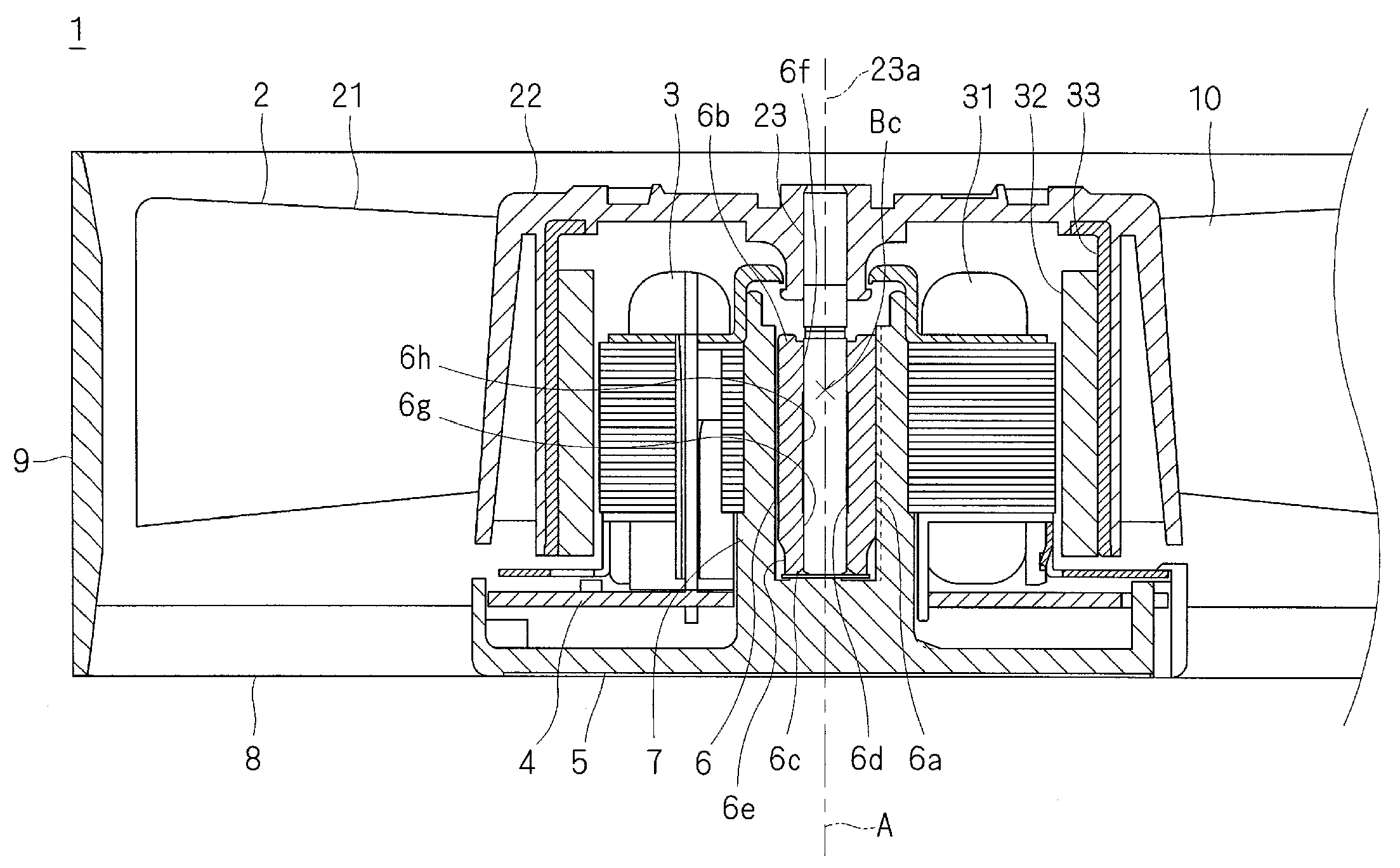
[0020]Referring to FIG. 1, a fan apparatus 1 preferably includes an impeller 2, a motor 3, a circuit board 4, a base portion 5, a sleeve 6, a sleeve support portion 7, a plurality of stationary vanes 8, and an outer frame portion 9. The impeller 2 preferably includes a plurality of rotor blades 21, a rotor blade support portion 22, and a rotating shaft 23. The motor 3 preferably includes an armature 31, which is a stationary motor component; and a rotor magnet 32 and a rotor holder 33, all of which are rotating motor components. Of these components, all components that are arranged to rotate on the rotating shaft 23 together with the rotating shaft 23 form portions of a rotating body 10. In other words, the impeller 2, the rotor magnet 32, and the rotor holder 33 form parts of the rotating body 10. In the following description, for the sake of convenience, the side where the impeller 2 is arranged and the side where the stationary vanes 8 are arranged, along an axial direction A of ...

second preferred embodiment

[0051]FIG. 5 is a cross-sectional view of a sleeve support portion 7 provided in a fan apparatus 1 to which a bearing structure according to a second preferred embodiment of the present invention is applied. The fan apparatus 1 according to the present preferred embodiment is essentially identical to the fan apparatus 1 according to the first preferred embodiment except in the structure of ribs 171 and 172. Accordingly, like portions are designated by like reference numerals and redundant description is omitted.

[0052]Referring to FIG. 5, in the present preferred embodiment, at least one of the ribs 171 and 172 provided on the inner surface 72a of the sleeve support portion 7 is not uniform in the radial dimension, i.e., in how far it projects from the inner surface 72a of the sleeve support portion 7 toward the shaft center 23a. This type of ribs will be referred to as “varied projection dimension ribs” as appropriate. In at least a partial section of the axial length (along the axi...

third preferred embodiment

[0063]FIGS. 7A and 7B are diagrams of a varied width rib 271 and a uniform width rib 272, respectively, which are provided on a sleeve support portion 7 of a fan apparatus 1 to which a bearing structure according to a third preferred embodiment of the present invention is applied, as viewed radially from the direction of the rotating shaft 23. The fan apparatus 1 according to the present preferred embodiment is essentially identical to the fan apparatus 1 according to the first preferred embodiment except in the structure of the varied and uniform width ribs 271 and 272. Accordingly, like portions are designated by like reference numerals, and redundant description is omitted.

[0064]In the present preferred embodiment, as illustrated in FIGS. 7A and 7B, at least one of the ribs 271 and 272 provided on the inner surface 72a of the sleeve support portion 7 is not uniform in width. This type of ribs will be referred to as “varied width ribs” as appropriate. In at least a partial section...


PUM


Abstract

A sleeve support portion is arranged to support a sleeve having a rotating shaft inserted therein such that the rotating shaft is rotatable. A plurality of ribs extending in an axial direction is provided on an inner surface of the sleeve support portion. The ribs are preferably spaced from each other in a circumferential direction centered on the rotating shaft, and arranged to make contact with at least a portion of the sleeve. The ribs include a plurality of types of ribs, each type of the ribs having a different axial position of an axial edge, on an axially opening portion side, of a contact surface thereof which is arranged to make contact with the sleeve.

Description

BACKGROUND OF THE INVENTION[0001]1. Field of the Invention[0002]The present invention relates to a bearing structure, a motor, and a fan apparatus.[0003]2. Description of the Related Art[0004]In known bearing structures for use in fans, motors, or the like, a plurality of ribs extending in an axial direction are typically provided on an inner surface of a cavity portion of a sleeve support portion arranged to support a sleeve having a rotating shaft inserted therein. The ribs press the sleeve, which is press fitted within the sleeve support portion, radially inward to retain the sleeve.[0005]Such bearing structures have some disadvantages. For example, when the pressing force applied by the ribs of the sleeve support portion onto the sleeve is too small, the positioning of the sleeve and the rotating shaft may become so insufficient that a problem, such as sway of the rotating shaft, may occur. On the other hand, when the pressing force applied by the ribs of the sleeve support port...

Claims


Application Information

Patent Timeline
Patent Type & Authority Applications(United States)
IPC IPC(8): F04D25/08F16C35/02H02K5/167
CPCF04D29/057F16C33/103F16C2360/46H02K5/1675F04D25/062F16C35/02
Inventor TESHIMA, HIROYOSHIMURAOKA, KOJIIDA, KIYOTO
Owner NIDEC CORP
Why Eureka
Try Eureka