
Linthium secondary battery improved safety and capacity

Active Publication Date: 2010-03-04
LG ENERGY SOLUTION LTD
View PDF5 Cites 23 Cited by
  • Summary
  • Abstract
  • Description
  • Claims
  • Application Information

AI Technical Summary

Benefits of technology

[0016]As a result of a variety of extensive and intensive studies and experiments to solve the problems as described above, the inventors of the present invention have found that, when electrode tap—electrode lead coupling regions are located at an upper-end contact region of a battery case of a secondary battery having an electrode assembly mounted in the battery case, not in a space of the battery case above the upper end of the electrode assembly, and the contact region of the battery case is bent, the occurrence of internal short circuits of the secondary battery according to the present invention due to external impacts, such as vibration or dropping, is effectively prevented, thereby further improving the safety of the secondary battery according to the present invention, and the inner space of the battery case is maximally utilized, whereby the secondary battery according to the present invention has a capacity higher than conventional secondary batteries having the same size as the secondary battery according to the present invention. The present invention has been completed based on these findings.
[0020]As previously described, the thermal welding parts may be formed along the edge of the battery case at the upper part of the contact region about the electrode tap—electrode lead coupling regions. According to circumstances, the thermal welding parts may be also formed in the lateral direction as well as the upper part of the electrode tap—electrode lead coupling regions. For example, the thermal welding parts may be formed at the outside region (a) of the cathode tap—cathode lead coupling region, at the outside region (b) of the anode tap—anode lead coupling region, and the middle region (c) between the electrode tap—electrode lead coupling regions. Alternatively, the thermal welding parts may be formed at the outside region (a) of the cathode tap—cathode lead coupling region and the outside region (b) of the anode tap—anode lead coupling region, or at the middle region (c) between the electrode tap—electrode lead coupling regions. When thermal welding is carried out at most of the contact region excluding the electrode tap—electrode lead coupling regions as described above, the sealability of battery case is increased, and the structural stability of the battery case against an external force applied to the battery case is further improved.
[0023]Preferably, insulative films are disposed at the upper-end contact region of the battery case, such that the insulative films surround the electrode taps, the electrode leads, and the top and bottom of the coupling regions between the electrode taps and the electrode leads, for improving sealability between the electrode taps and the electrode leads and the battery case and, at the same time, for securing electrical insulation between the electrode taps and the electrode leads and the battery case.
[0025]The electrode assembly is basically constructed in a structure in which the cathodes and the anodes are sequentially stacked one on another while separators are disposed respectively between the cathodes and the anodes. According to circumstances, the separators may have a length enough that the ends of the separators are adjacent to the upper-end contact region or partially overlap with the upper-end contact region, whereby the safety of the battery is further improved.

Problems solved by technology

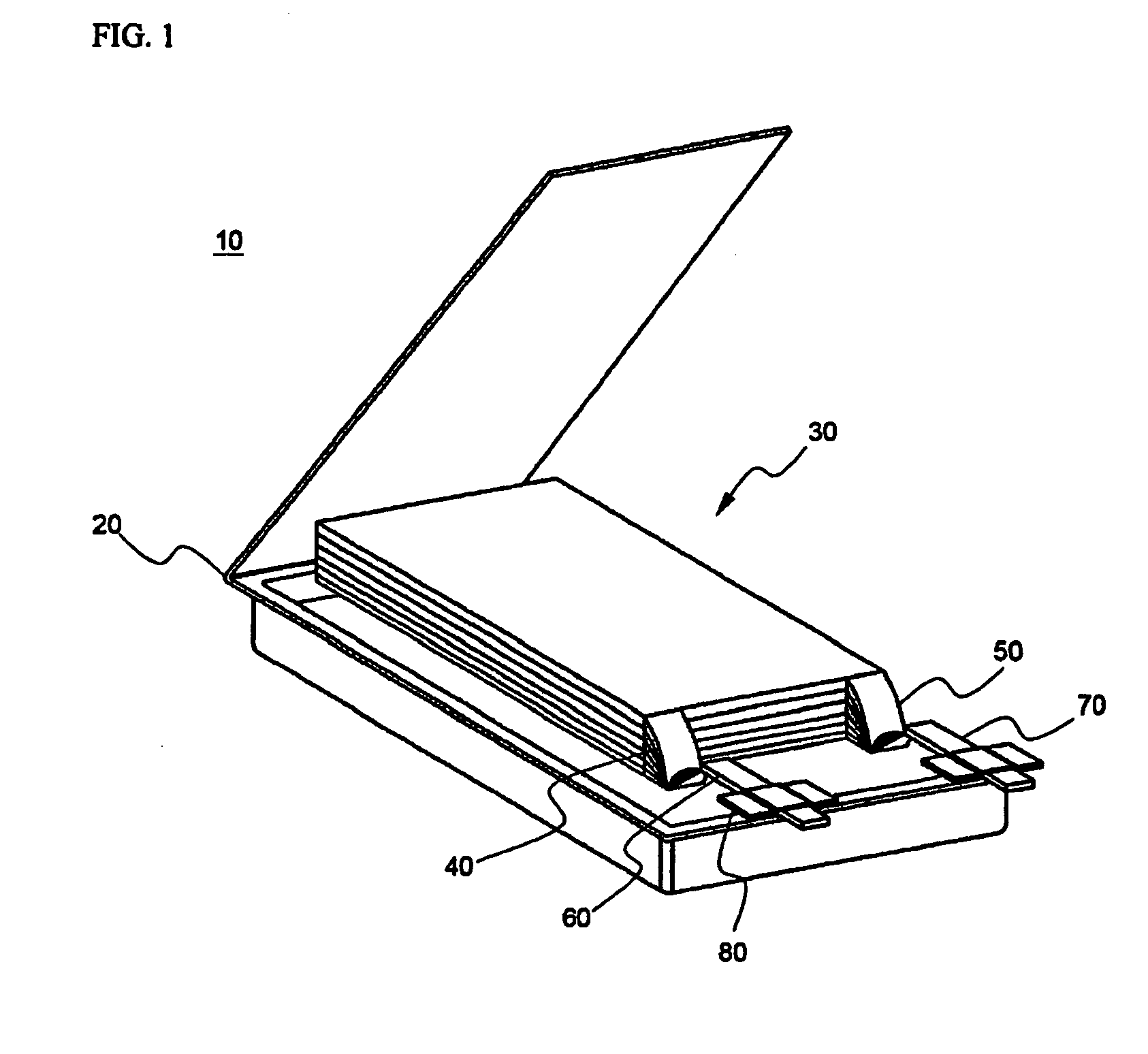
However, such V-form regions have several problems in the aspect of capacity and safety of the battery.
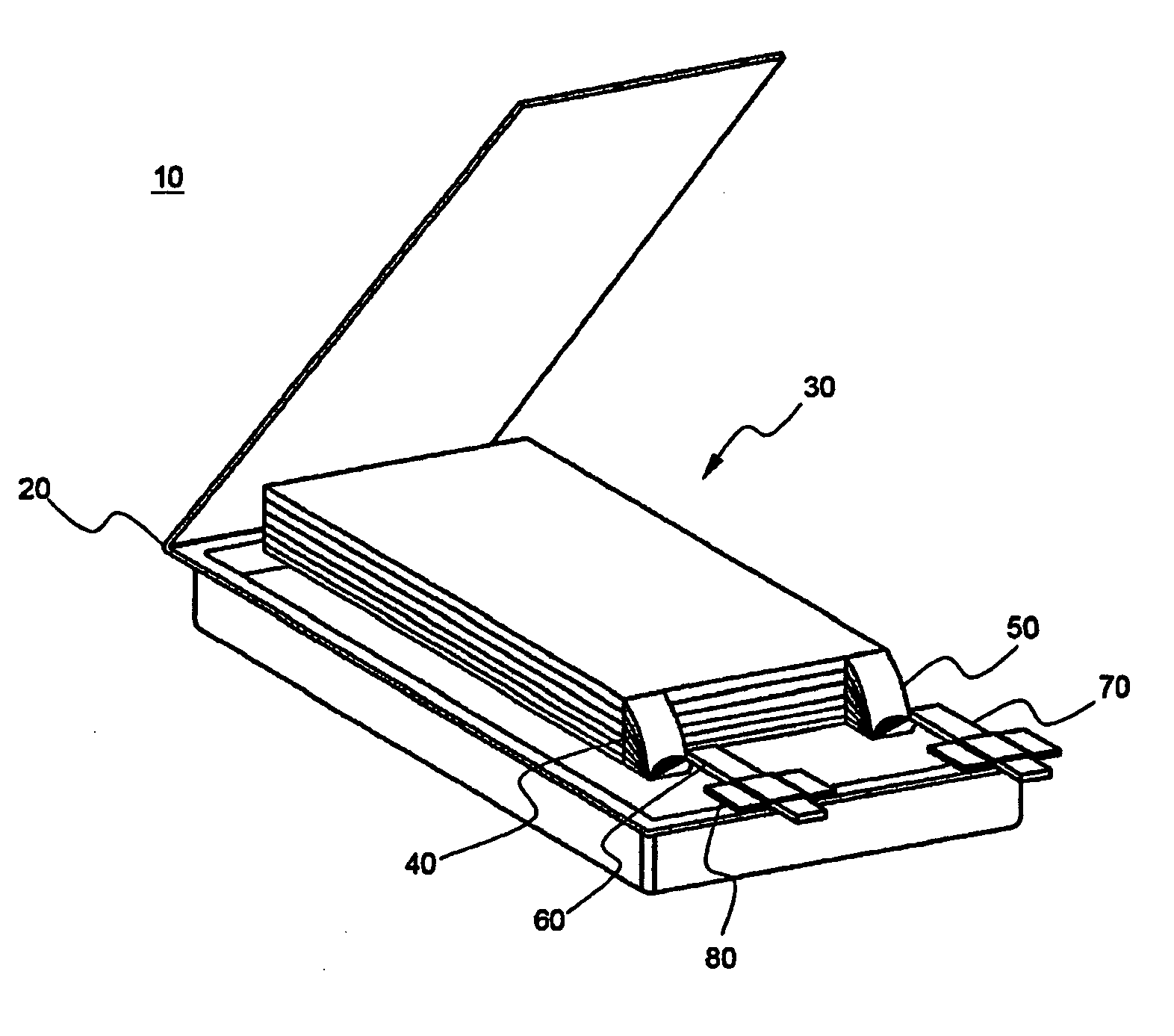
However, the V-form regions restrict the size of the electrode assembly 30 mounted in the battery case 20 with the result that the capacity of the battery is decreased.
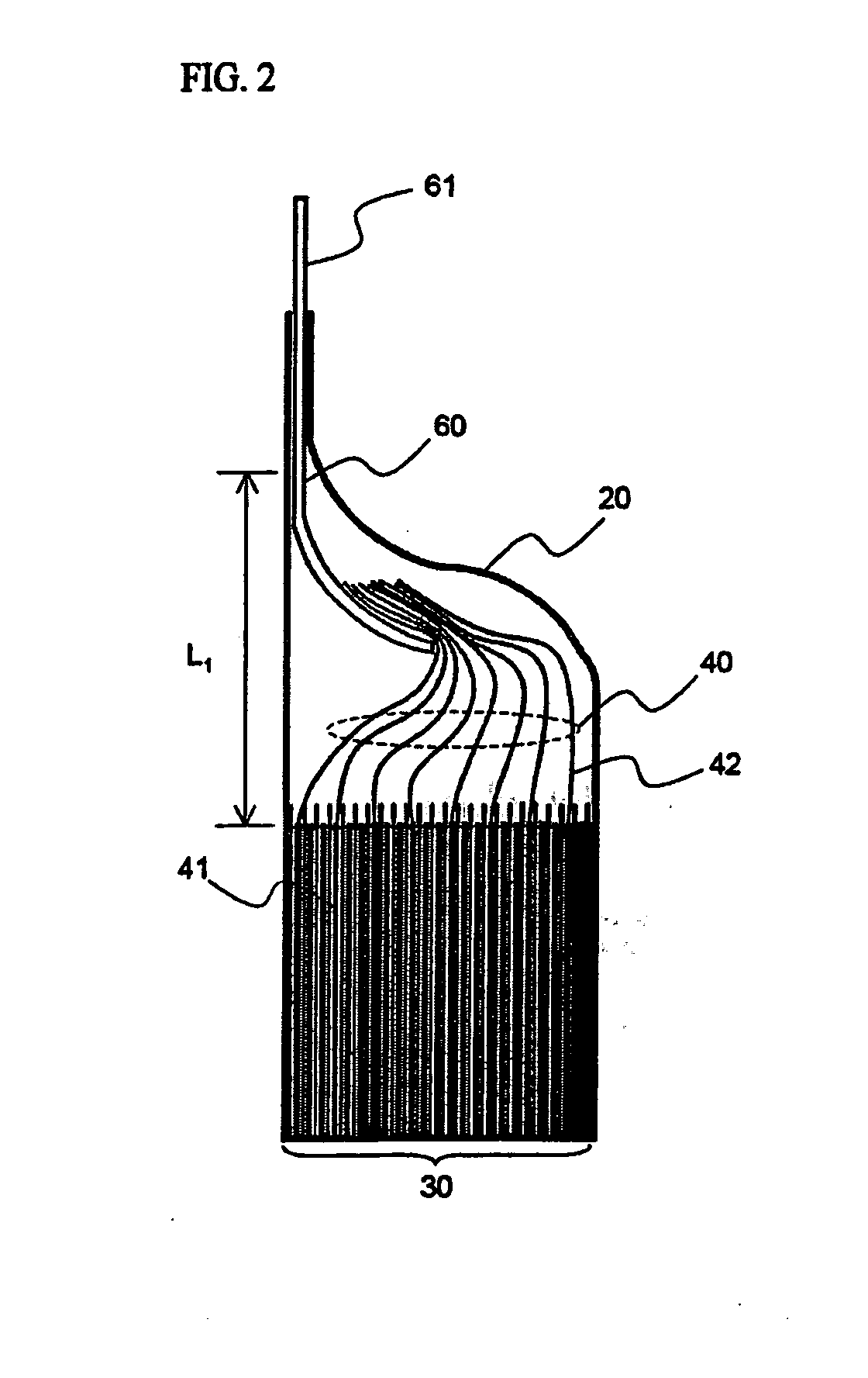
Especially, such internal short circuits occur due to the contact between some of the cathode taps below the welded bunch and the outermost anodes.

Method used


Image

  • Linthium secondary battery improved safety and capacity
  • Linthium secondary battery improved safety and capacity
  • Linthium secondary battery improved safety and capacity

Examples


Embodiment Construction

[0038]Now, preferred embodiments of the present invention will be described in detail with reference to the accompanying drawings. It should be noted, however, that the scope of the present invention is not limited by the illustrated embodiments.

[0039]FIG. 4 is an exploded perspective view illustrating a pouch-shaped secondary battery according to a preferred embodiment of the present invention, and FIG. 5 is a front see-through view illustrating upper-end and side contact regions of a battery case, in which an electrode assembly is mounted, of the pouch-shaped secondary battery of FIG. 4 in a state in which the upper-end and side contact regions of the battery case are sealed.

[0040]Referring to these drawings, the pouch-shaped secondary battery 100 includes an electrode assembly 300 having cathode taps 310 and anode taps welded to a cathode lead 410 and an anode lead 420, respectively, and a battery case 200 for receiving the electrode assembly 300.

[0041]The battery case200 include...


PUM


Abstract

Disclosed herein is a secondary battery having an electrode assembly constructed in a structure in which a plurality of electrodes are stacked, while separators are disposed respectively between the electrodes, and electrode taps of the electrodes are connected with each other, the electrode assembly being mounted in a battery case, wherein regions where the electrode taps are coupled to electrode leads (electrode tap-electrode lead coupling regions) are located at an upper-end contact region of the battery case, and the contact region is bent in the thickness direction of the battery, whereby the electrode assembly is separated from an inner space of the battery case.

Description

FIELD OF THE INVENTION[0001]The present invention relates to a lithium secondary battery having increased safety and capacity, and, more particularly, to a secondary battery having an electrode assembly constructed in a structure in which a plurality of electrodes are stacked, while separators are disposed respectively between the electrodes, and electrode taps of the electrodes are connected with each other, the electrode assembly being mounted in a battery case, wherein regions where the electrode taps are coupled to electrode leads (electrode tap—electrode lead coupling regions) are located at an upper-end contact region of the battery case, and the contact region is bent in the thickness direction of the battery, whereby the electrode assembly is separated from an inner space of the battery case.BACKGROUND OF THE INVENTION[0002]As mobile devices have been increasingly developed, and the demand of such mobile devices has increased, the demand for batteries has also sharply increa...

Claims


Application Information

Patent Timeline
IPC IPC(8): H01M6/12H01M2/00H01M2/08H01M50/124H01M50/178H01M50/54H01M50/55H01M50/553H01M50/566
CPCH01M2/021H01M2/0275H01M2/0287H01M2/266Y02E60/122H01M10/0525H01M10/0565H01M10/0585H01M10/425H01M2/34Y02E60/10H01M50/124H01M50/54Y02P70/50H01M50/178H01M50/55H01M50/553H01M50/566H01M50/20
Inventor CHOI, BYUNGJINLEE, HANG MOKAHN, CHANG BUMLEE, WOOYONGHWANG, SUNG-MINHYUN, OH YOUNG
Owner LG ENERGY SOLUTION LTD
Learn More