Therapeutic Compression Garments

Inactive Publication Date: 2010-03-04
FARROW INNOVATIONS
View PDF46 Cites 75 Cited by
  • Summary
  • Abstract
  • Description
  • Claims
  • Application Information

AI Technical Summary

Benefits of technology

[0023]In accordance with aspects of the present invention, an apparatus, method and system for facilitating therapeutic compression having controlled and repeatable baseline compressions that provide intuitive feedback to

Problems solved by technology

While useful in some applications, the Unna boot is subject to a number of limitations.
Therefore, controlled baseline compression is difficult to ascertain because there is no feedback to guide when appropriate compression levels are obtained.
Furthermore, as edema reduces, the boot loses compression and allows bandages to shift, possibly increasing drainage in the case of any wounds present.
A further limitation is that the rigid shell boot can cause pressure ulceration if it dries with too much pressure over bony prominences or other sensitive tissue areas.
Patients undergoing total contact cast therapy are commonly unable to feel when a rigid cast is not properly applied causing dangerous pressure points or when padding is insufficient, exposing the skin to the rough inner surface of the cast.
There are limitations to these type garments.
The garment does not form fit well as it is relatively nonelastic.
The garment loosens as edema reduces, and requires more frequent readjustments, and inelastic products do not function well over joints Finally, there is no intuitive way that a user can control the baseline or resting compression as there is no feedback from the garment.
The Coban 2 layer compression banda

Method used


Image

  • Therapeutic Compression Garments
  • Therapeutic Compression Garments
  • Therapeutic Compression Garments

Examples


Embodiment Construction

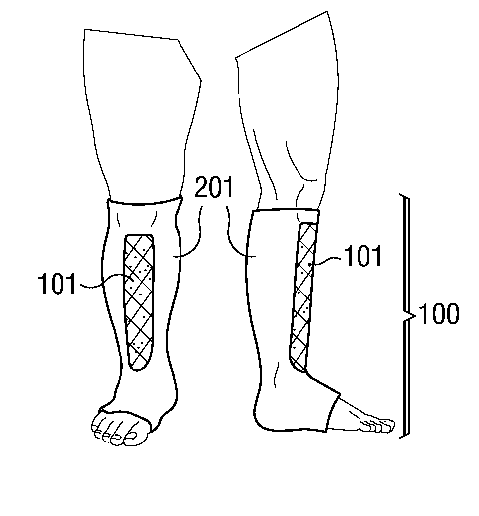
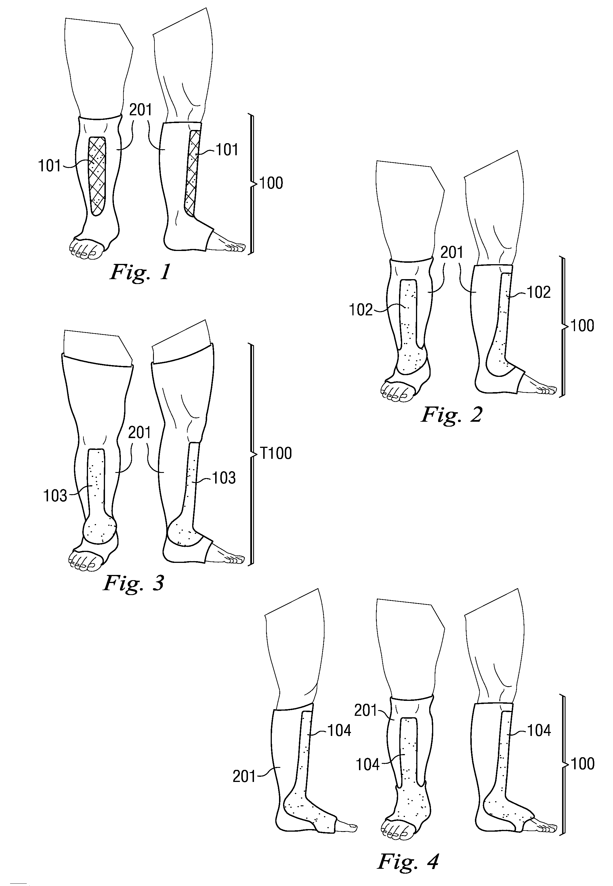
[0092]The present disclosure relates generally to treatment of edema and, more specifically, to a liner to be used under a device for applying compressive pressure to a person's body in order to facilitate reduction of interstitial fluids from a body trunk and / or limb extremity and to provide support and fatigue relief.

[0093]It is to be understood that the present disclosure provides many different embodiments, or examples, for implementing different features of various embodiments. Specific examples of components and arrangements are described below to simplify the present disclosure. These are, of course, merely examples and are not intended to be limiting. In addition, the present disclosure may repeat reference numerals and / or letters in the various examples. This repetition is for the purpose of simplicity and clarity and does not, in itself, dictate a relationship between the various embodiments and / or configurations discussed. Moreover, the formation of a first feature over o...


PUM


Abstract

A therapeutic compression apparatus includes a liner having a tubular body portion with a proximal opening for receiving a limb of a patient. The tubular body portion includes an inside region with an inside circumference that is sized to extend about and in contact with the limb. The inside circumference is substantially identical to a circumference of the limb at a respective area of contact. The tubular body portion includes an outside region having an outside circumference that varies from the inside circumference at respective cross-sections through the tubular body, such that a first function of a ratio of the difference between the inside circumference and the outside circumference at a respective cross-section through the tubular body, divided by the inside circumference at said respective cross-section, and a second function of the inside circumference at said respective cross-section determines, in part, a pressure exerted on the limb at said cross-section when compression is applied by said therapeutic compression apparatus.

Description

PRIORITY[0001]This application claims priority to and the benefit of the filing date of U.S. Application No. 61 / 092,459, filed Aug. 28, 2008, incorporated herein in its entirety by reference.TECHNICAL FIELD[0002]This disclosure relates to apparatus, methods and systems for treating medical conditions by application of controlled compression to general and specific areas of a patient's body.BACKGROUND OF THE INVENTION[0003]Excessive interstitial fluid accumulation, referred to as edema, may arise from a variety of illnesses and conditions, including venous valvular insufficiency, postphlebotic syndrome, and lymphedema. Compression apparatus method and systems control edema by reduction of interstitial fluids which increases nutrient delivery to tissues, removes waste from tissues, relieves pain from swelling, and decreases risk of infection. However, prior-art compression technologies have certain drawbacks as explained below.[0004]Wounds complicate the problem because traditional co...

Claims


Application Information

Patent Timeline
IPC IPC(8): A61F13/06A61N1/02A61L15/00
CPCA61F13/08A61F13/041
Inventor FARROW, WADE P.CREIGHTON, BARRY L.
Owner FARROW INNOVATIONS
Why Eureka
Try Eureka