Electronic device and error management system

a technology of error management system and electronic devices, applied in the direction of electrographic process, fault response, instruments, etc., can solve the problems of fatal errors, trivial errors, and hardware devices and software included in electronic devices that malfunction in many ways, and achieve the effect of reducing the number of errors

Inactive Publication Date: 2010-03-04
KYOCERA DOCUMENT SOLUTIONS INC
View PDF9 Cites 32 Cited by
  • Summary
  • Abstract
  • Description
  • Claims
  • Application Information

AI Technical Summary

Benefits of technology

[0017]Namely, an electronic device according to an aspect of the present invention includes: a memory unit in which a plurality of error information is stored; and a control unit selecting from among the plurality of error information, an error information such that at least one of a type and a frequency of the error that occurred satisfies / satisfy a predetermined condition, the control unit also making the memory unit save the error information.
[0018]On the other hand, an electronic device according to another aspect of the present invention includes: a display unit; a memory unit storing an image displayed on the display unit; a communication unit communicating with an external party; a control unit converting the image displayed on the display unit when an error occurred into a first image file and storing this first image file as a first error information to the memory unit, displaying an error notification screen on the display unit indicating that the error occurred, converting the error notification screen displayed on the display unit into a second image file and storing this second image file as a second error information to the memory unit; and an output control unit outputting the first error information and the second error information according to an instruction from the external party.
[0019]On the other hand, an electronic device according to an aspect of the present invention includes: a display unit; a display screen storing unit storing a screen data being a basis of an image displayed on the display unit; a preparation screen storing unit storing the screen data corresponding to an operation performed in a background and the screen data which can be displayed after the image displayed on the display unit; an error information storing unit storing an error information; a memory control unit making the error information storing unit store the screen data saved by the display screen storing unit when an error occurs, and the screen data saved by the preparation screen storing unit, respectively as a first error information; and an output control unit outputting the first error information based on an instruction from an external party.

Problems solved by technology

These hardware devices and software included in the electronic devices malfunction in many ways due to multiple causes occurring while various processings such as operational processing, communication processing, and standby processing are carried out.
For instance, when the electronic device includes software with a design defect, grave malfunctions occur.
However, errors include fatal errors and trivial errors.
Meanwhile, error information concerning trivial errors is not necessarily used to analyze errors.
As a result, error information concerning trivial errors is sometimes wasted even though it is saved.
When such trivial errors occur frequently, unnecessary error information accumulates in the memory field in which error information is stored.
Consequently, there will not be enough free space available in the memory field.
Thus, the saved application screen might not be used to identify the cause of the malfunction.
Consequently, even though the error information is stored in the memory due to the occurrence of the error, the personnel analyzing the malfunction cannot recognize immediately after the error occurs that the error information has been stored.
Even though the reset application screen is stored based on this framework, there may not be any information left that would be useful for analyzing the malfunction.
Furthermore, even though the operation at the time of the error can be recognized through the saved application screen, the operation before the error and the log of the user's operation cannot be recognized.
In this way, the frameworks based on the related art cannot adequately save the information useful for analyzing the malfunction.
Therefore, the malfunction cannot be analyzed efficiently.

Method used


Image

  • Electronic device and error management system
  • Electronic device and error management system
  • Electronic device and error management system

Examples


first embodiment

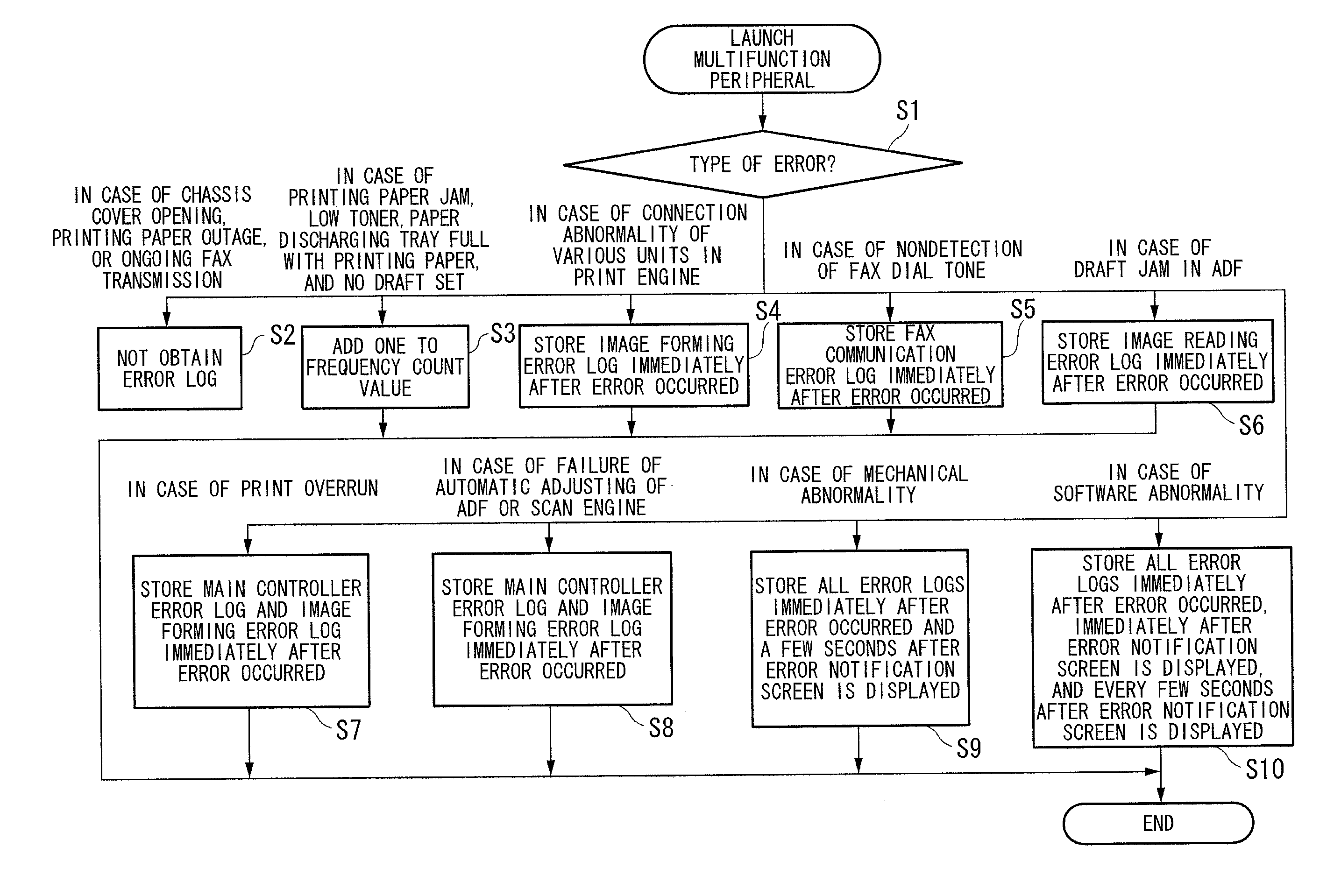
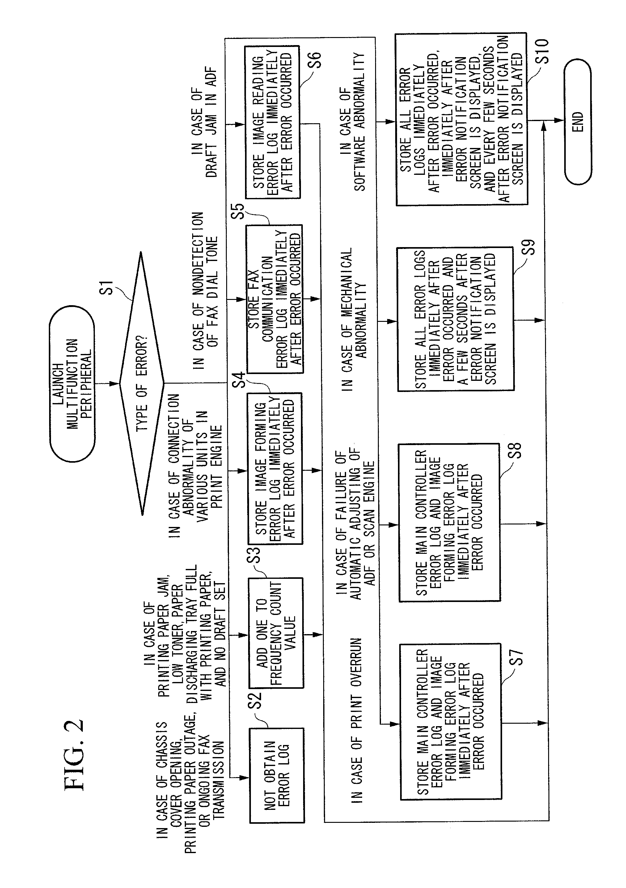
[0049]Hereunder, an electronic device according to the present invention is described with reference to FIGS. 1 and 2. The above embodiment concerns a multifunction peripheral equipped with a copying feature, a printing feature, and a facsimile sending / receiving feature, the multifunction peripheral being a type of an image forming device.

[0050]The electronic device according to an aspect of the present invention includes: a memory unit in which a plurality of error information is stored; and a CPU 1a selecting from among the plurality of error information, an error information such that at least one of a type and a frequency of the error that occurred satisfies / satisfy a predetermined condition, the CPU 1a also making the memory unit save the error information.

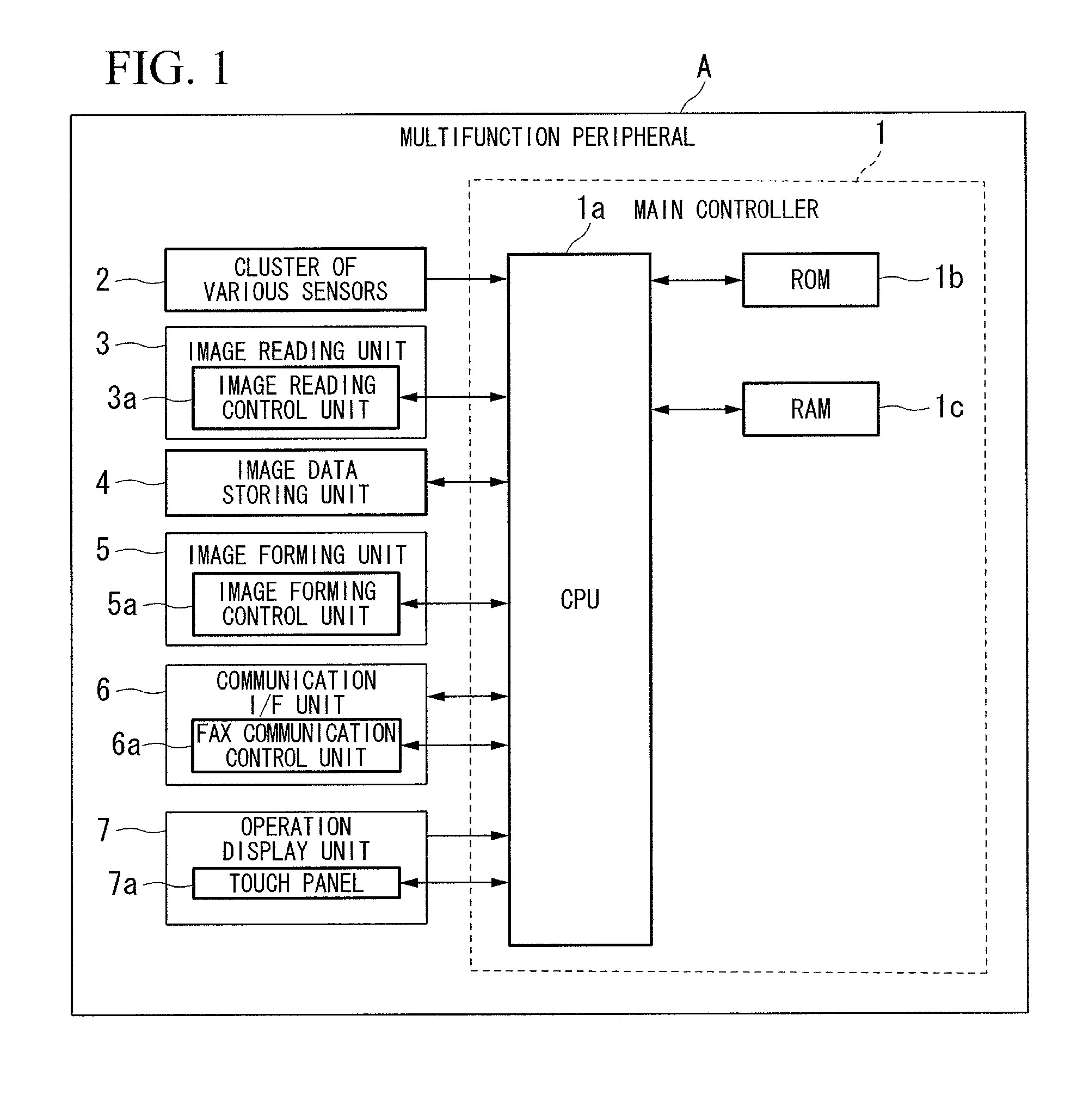
[0051]First, the functions and configuration of a multifunction peripheral A are described with reference to FIG. 1. The multifunction peripheral A includes a main controller 1, a cluster of various sensors 2, an image readin...

second embodiment

[0083]Hereunder, the electronic device according to the present invention is described with reference to FIGS. 3, 4, 5, and 6. The above embodiment concerns a multifunction peripheral equipped with a copying feature, a printing feature, and a facsimile sending / receiving feature, the multifunction peripheral being a type of an image forming device.

[0084]First, the functions and configuration of a multifunction peripheral A100 are described with reference to FIG. 3. The multifunction peripheral A100 includes a CPU (Central Processing Unit) 101, a ROM (Read Only Memory) 102, a RAM (Random Access Memory) 103, a cluster of various sensors 104, a paper transporting unit 105, an image reading unit 106, an image data storing unit 107, an image forming unit 108, a communication I / F unit 109, an operation display unit 110, and an error information storing unit 111.

[0085]The CPU 101 controls the overall operations of the multifunction peripheral A100 based on a control program stored in the RO...

third embodiment

[0111]Hereunder, the present invention is described with reference to FIGS. 7, 8, 9, 10, and 11. The above embodiment concerns a multifunction peripheral equipped with a copying feature, a printing feature, and a facsimile sending / receiving feature, the multifunction peripheral being a type of an image forming device included in the electronic device according to the present invention. The above embodiment also concerns an error management system including the multifunction peripheral.

[0112]First, the system configuration of the error management system A200 is described with reference to FIG. 7.

[0113]As shown in FIG. 7, the error management system A200 includes a multifunction peripheral B200, a supervisory computer C200, and a public network D200.

[0114]The multifunction peripheral B200 performs a copying process based on instructions to make copies. In addition, the multifunction peripheral B200 performs a printing process based on instructions from a client computer to make printo...


PUM


Abstract

An electronic device including: a memory unit in which a plurality of error information is stored; and a control unit selecting from among the plurality of error information, an error information such that at least one of a type and a frequency of the error that occurred satisfies/satisfy a predetermined condition, the control unit also making the memory unit save the error information.

Description

[0001]The present application claims priority on Japanese Patent Application No. 2008-218268, filed Aug. 27, 2008; Japanese Patent Application No. 2008-220134, filed Aug. 28, 2008; Japanese Patent Application No. 2008-218269, filed Aug. 27, 2008; Japanese Patent Application No. 2008-260907, filed Oct. 7, 2008; Japanese Patent Application No. 2008-260908, filed Oct. 7, 2008; and Japanese Patent Application No. 2008-296653, filed Nov. 20, 2008; the contents of which are incorporated herein by reference.BACKGROUND OF THE INVENTION[0002]1. Field of the Invention[0003]The present invention relates to an electronic device and an error management system.[0004]2. Description of the Related Art[0005]Various electronic devices such as personal computers, cellular phones, printers, multifunction peripherals, and household electrical appliances are composed of hardware devices such as CPU (Central Processing Unit) and memory, as well as software executed by the CPU. These hardware devices and s...

Claims


Application Information

Patent Timeline
Patent Type & Authority Applications(United States)
IPC IPC(8): G06F11/07
CPCG03G15/55G03G15/5079G06F11/076G06F11/0769G06F11/0781H04N1/00432H04N1/00472H04N1/00474H04N1/00482H04N1/32609H04N1/3263H04N1/32635H04N1/32641H04N2201/0094H04N2201/3215H04N2201/3219H04N2201/3221H04N2201/3273H04N2201/3274G03G15/502G03G2215/00109G06F3/121G06F3/1207G06F3/122G06F3/1234G06F3/1259G06F3/1273G06F3/1285G06F11/0733
Inventor YAMASHIRODANI, MASAYUKINODA, TATSUOMATSUSAKA, TETSUYAHAMAKAWA, TAKESHIIKAZAKI, AKIHIKOHIGASHIMORI, TOSHIHIDE
Owner KYOCERA DOCUMENT SOLUTIONS INC
Why Eureka
Try Eureka