

Injection of refrigerant in system with expander
- Summary
- Abstract
- Description
- Claims
- Application Information
AI Technical Summary
Benefits of technology
Problems solved by technology
Method used
Image

Examples
embodiment 40
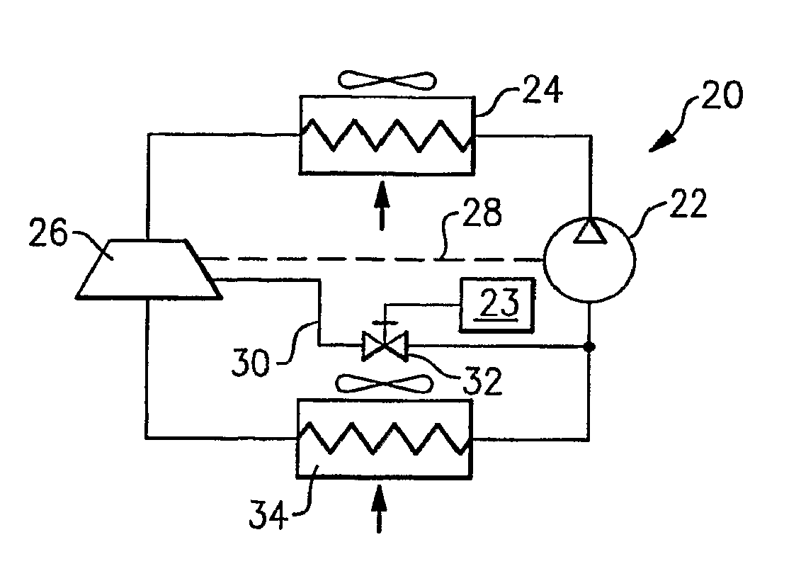
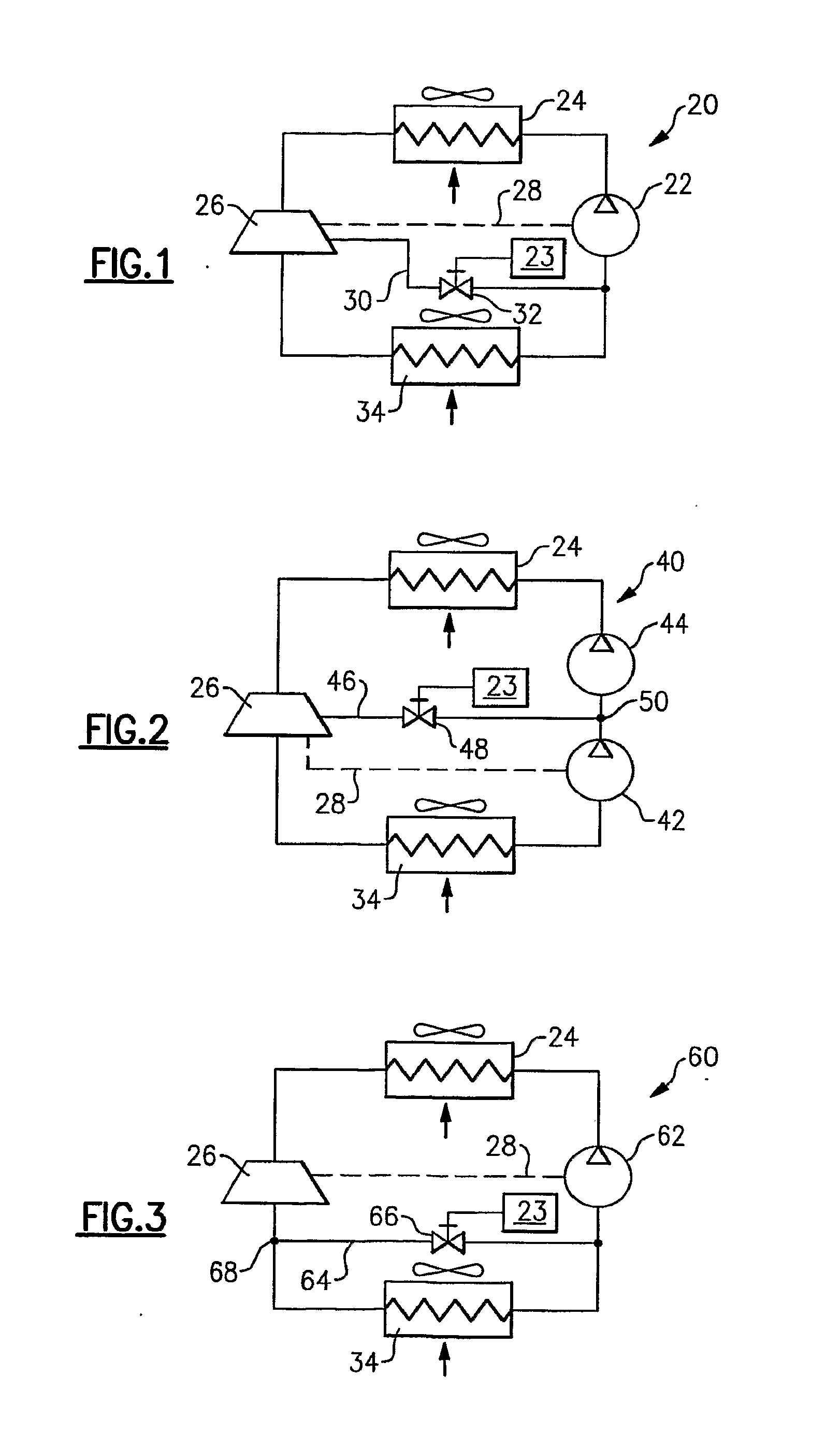
[0022]FIG. 2 shows another embodiment 40, wherein there is a two-stage compressor that consists of two compression stages 42 and 44. As known, two compression stages 42 and 44 can be two separate compressor units or two compression stages within the same compressor, as for instance, two banks of cylinders, in the case of a reciprocating compressor. The power supply connection 28 only assists in driving one lower stage compressor 42. It is understood that a higher stage compressor 44 can take advantage of energy recovery from the expander 26 instead. The refrigerant leaving the expander 26 in this embodiment is returned through a return line 46 into an intermediate return point 50 between the compression stages 42 and 44. The return line 46 also has a control valve 48. The control valve 48 would operate similar to the control valve 32. This embodiment is distinct in that the return point 50 for the refrigerant return line 46 is at an intermediate location between the two compression ...
embodiment 60
[0023]FIG. 3 shows another embodiment 60, which is similar to the FIG. 1 embodiment. However, a return line 64 is taken from a point 68 downstream of the expander 26. Again, a control valve 66 is controlled such that the amount of refrigerant reaching the compressor 62 is tailored to achieve desired characteristics for the refrigerant system 60. In this arrangement, an orifice or another flow restriction device can be added between the point 68 and entrance to the evaporator 34 to assure that there is sufficient pressure differential to drive the desired amount of injected refrigerant through the refrigerant return line 64. Further, in this embodiment, the injected refrigerant participates in the entire expansion process such as maximum energy amount is recovered from the expansion process, improving performance (capacity and efficiency) of the refrigerant system 60.
[0024]While in the embodiments shown in FIGS. 1-3 at least a portion of refrigerant has been tapped from a location wh...
PUM
 Abstract
Description
Claims
Application Information