
Felt with seam for paper manufacture

a technology of paper manufacturing and felt, applied in the field of felt, can solve the problems of increasing the difficulty of insertion of the core line member, increasing the difficulty of insertion of the seam thread s, and difficulty in engaging the seam loop l in an alternating arrangement, so as to achieve smooth intermeshing of the seam loop, stable meshing, and more stably positioned

Inactive Publication Date: 2010-03-11
ICHIKAWA ELECTRIC CO LTD
View PDF7 Cites 6 Cited by
  • Summary
  • Abstract
  • Description
  • Claims
  • Application Information

AI Technical Summary

Benefits of technology

[0017]An object of the invention is to solve the above-mentioned problems, and to provide a seam felt for paper manufacture having ends that can be joined more quickly and easily so that installation of the felt in a papermaking machine can be carried out more quickly and easily.
[0025]One of the advantages of the Invention is that, with groups of seam loops each composed of two or more loops of MD yarn arranged side by side, even if the yarns forming the seam loops are thin, the seam loops at the opposite ends of the ground fabric can be brought easily into stable meshing relationship easily when the ends are connected while the felt is being installed in a papermaking machine.
[0026]Another advantage is that if the seam loops in a group are joined together by adhesive bonding or fused together, the group becomes more difficult to displace either in the cross-machine direction or in directions transverse to the faces of the felt. Therefore, the seam loops can be more stably positioned in the desired configuration so that intermeshing of the seam loops can be carried out smoothly.

Problems solved by technology

If the meshing of the seam loops L is poor, the insertion of the seam thread S can require a considerable amount of time and effort.
When one or more of the loops becomes smaller, the space for receiving the seam thread S, formed by the intermeshing loops, becomes uneven, increasing the difficulty of insertion of the core line member.
In addition, the engagement of the seam loops L in an alternating arrangement is by its nature complicated and difficult.
The difficulty of arranging the loops in proper intermeshing relationship also increases as the diameter of the MD direction yarns decreases, making the assembly of the felt more time-consuming.

Method used


Image

  • Felt with seam for paper manufacture
  • Felt with seam for paper manufacture
  • Felt with seam for paper manufacture

Examples


example 1

[0049]In this example, yarn A was employed as the MD yarns, and yarn B was used as the CD yarns. The ground fabric BA1 was fabricated by 3 / 1 1 / 3 warp double weaving. A cross-sectional view of the weave in the CD direction is shown in FIG. 6. For the MD yarns, two yarns set side by side were supplied to the weaving machine so that the seam loops are formed with two yarns constituting one group. For the ground fabric BA1, the MD yarns were turned back on themselves at the position of the seam thread S as shown in FIG. 7.

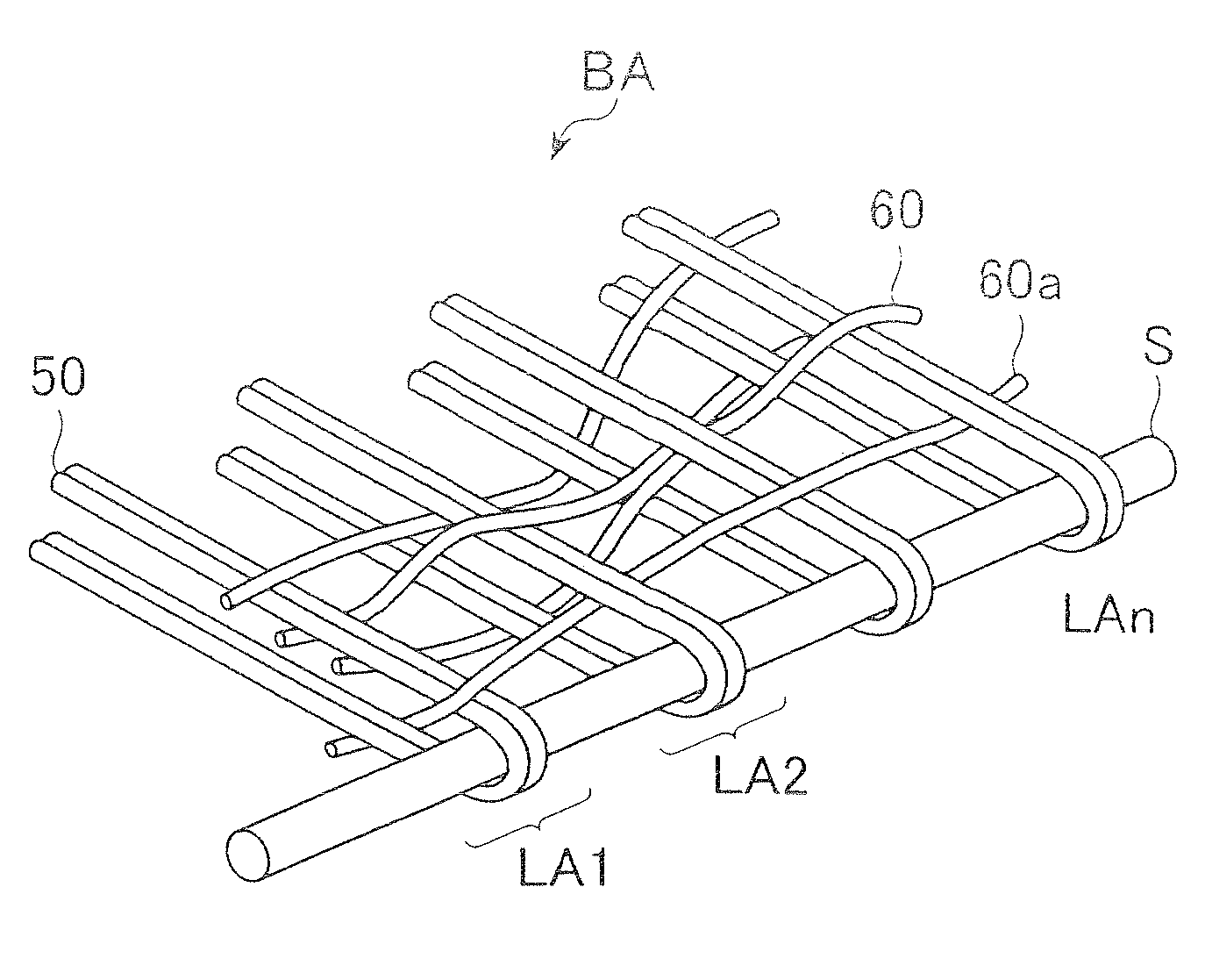
[0050]FIG. 7 is a perspective view of the seaming section of the ground fabric BA1 showing groups LB1 and LA2 of seam loops at one end, and a groups LB1 at the other end, joined together by a seam thread S form and endless felt.

[0051]Following weaving, the ground fabric BA1 was drawn out from the weaving machine, and hung on a pair of rolls. Then, the ground fabric was subjected to heat treatment, using a heating device (not shown). The heating device can be installed ...

example 2

[0054]As in the first example, in this example, yarn A was employed as the MD yarn, and yarn B was used as the CD yarn. The ground fabric was woven in 3 / 1 1 / 3 warp double weave.

[0055]In this case, the supply speed of the CD yarn and the supply speed of the MD yarn were adjusted on the weaving machine so that the seam loops of each group were separated by a distance close to the diameter of yarn A. A ground fabric having a 0.2 mm seam loop interval in the seam loop groups was obtained. The remaining conditions were the same as in Example 1. Thus, the seam felt 2 of the present invention was completed.

example 3

[0056]In this example, yarn C was used as the MD yarn, and yarn B was employed as the CD yarn, the ground fabric was prepared in he same manner as that in Example 1. The ground fabric was then subjected to heat setting, as in example 1, to stabilize the forms of the groups of seam loops. In this example, the heat set temperature was adjusted to at least 180 degrees Celsius, causing the copolymerized nylon sheath of the yarn C to melt, thereby joining the seam loops of each group. In other respects, the process was the same as in Example 1. Thus, the seam felt 3 of the present invention was completed.


PUM


Abstract

In a seam felt for paper manufacture, seam loops formed at opposite ends of a length of ground fabric to which layers of batt fiber are integrated by needle punching, are formed as groups of loops composed of machine direction yarns. When the opposite ends of the ground fabric are brought together, the groups of loops are intermeshed in an alternating arrangement to form a common bore for receiving a seam thread by which the intermeshed groups of loops are secured together. The loops of each group can be held together by adhesive bonding, or by heat adhesion if the machine direction yarns are core-in-sheath composite fibers wherein the sheath has a lower melting point than that of the core.

Description

CROSS-REFERENCE TO RELATED APPLICATION[0001]This application claims priority on the basis of Japanese patent application 232191 / 2008, filed Sep. 10, 2008. The disclosure of Japanese application 232191 / 2008 is hereby incorporated by reference.FIELD OF THE INVENTION[0002]This invention relates to a felt employed in the press part of a paper manufacture machine, and particularly to a felt having seam loops, hereinafter sometimes be referred to simply as a “seam felt”.BACKGROUND OF THE INVENTION[0003]In a paper manufacturing process, water is conventionally squeezed out from a wet paper web in the press part of a papermaking machine by means of a needle felt and a pair of press rolls. It is known to utilize a felt formed into an endless belt by connecting both ends of an elongated felt by means of seam loop. As shown in FIG. 1, the elongated felt F is formed into the shape of a belt, so that the loops L at its ends can be brought together and connected.[0004]As shown in FIG. 2, the felt...

Claims


Application Information

Patent Timeline
Patent Type & Authority Applications(United States)
IPC IPC(8): D21F7/10
CPCD21F7/10
Inventor OGIWARA, YASUYUKI
Owner ICHIKAWA ELECTRIC CO LTD
Learn More