This helps you quickly interpret patents by identifying the three key elements:
Problems solved by technology
Method used
Benefits of technology
Benefits of technology
[0049]According to the present invention, the microwave heating appliance capable of achieving a locally concentrated heating in response to the purpose while achieving the uniform heating of the overall heating chamber in a normal mode can be provided.
Problems solved by technology
By the way, it has been known that a wavelength of the microwave used in the microwave oven is about 120 mm, strong and weak electric field distributions (referred to as “field strength distributions” hereinafter) are caused in the heating chamber, and thus unevenness in heating is caused by a synergistic effect of such unevenness and influences of the shape of the heated subject and its physical property.
In the prior art, in this type microwave heating appliance, one radiation antenna is provided and is rotated and driven in operation, but it is difficult to heat locally a center area of the heating chamber.
However, the microwave heating appliance does not always heat a large amount of foods, although such heating appliance has a wide heating chamber.
Method used
Image
Click on the blue label to locate the original text in one second.
Reading with bidirectional positioning of images and text.
Examples
embodiment 1
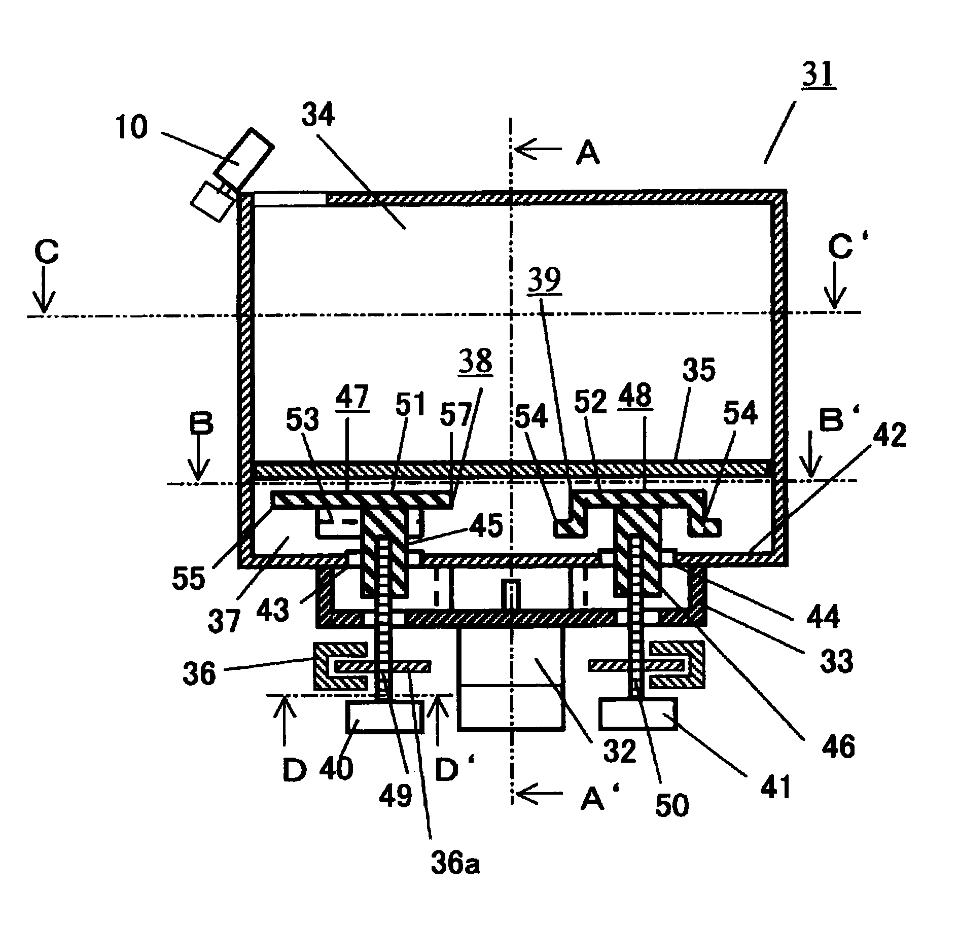
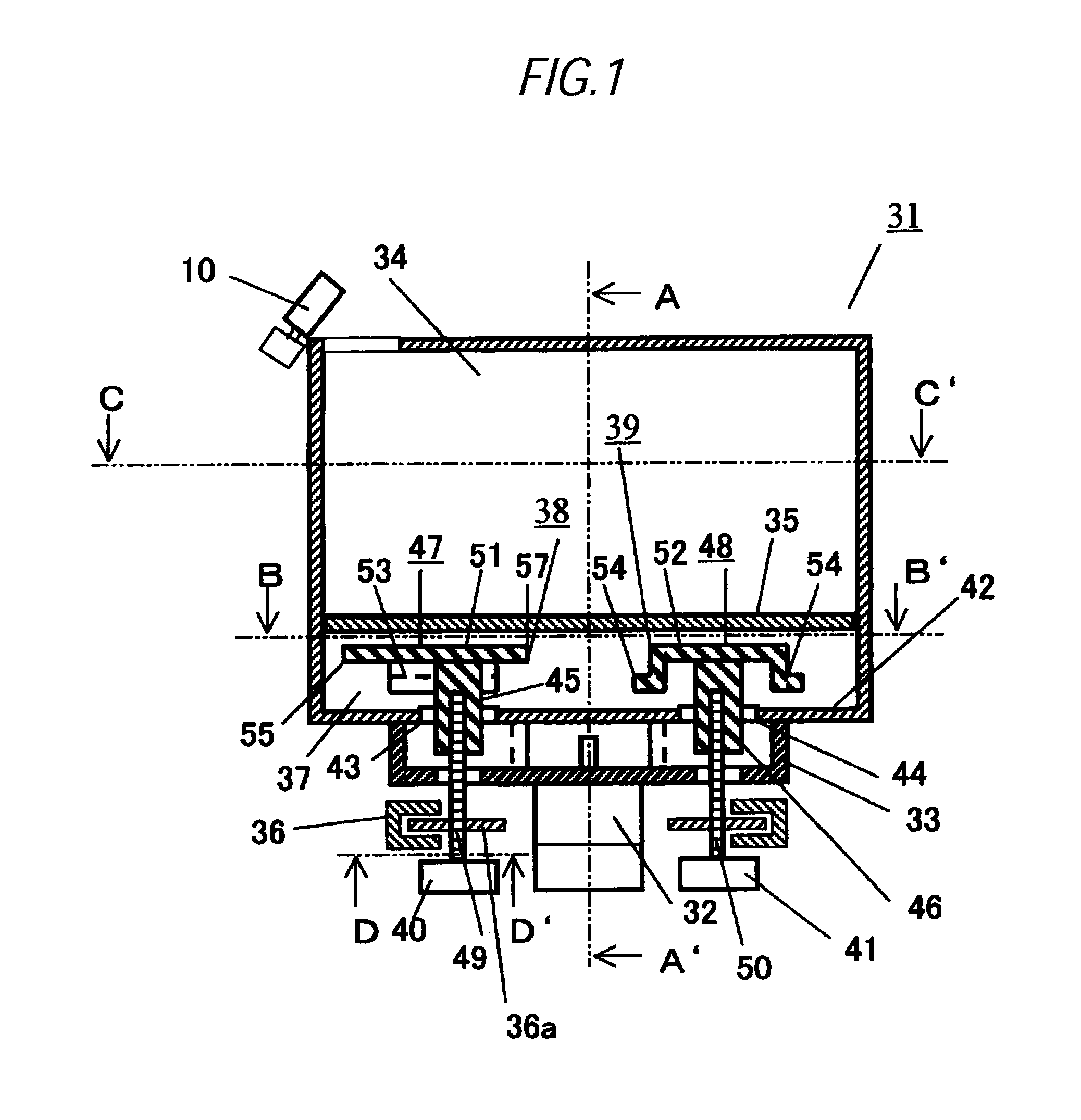
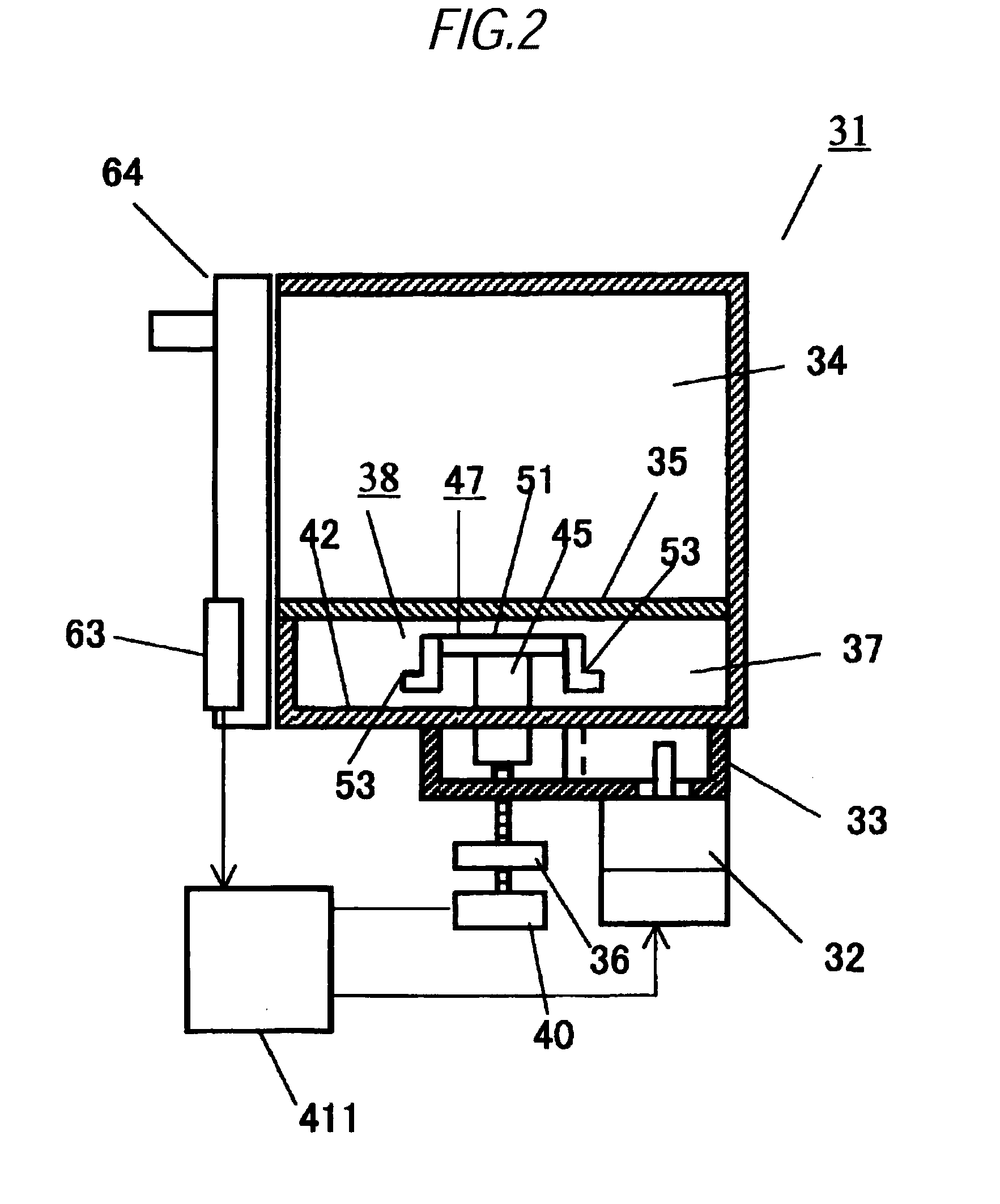
[0080]FIG. 1 to FIG. 3 are configurative views of a microwave oven 31 as a typical microwave heating appliance of according to the present invention. FIG. 1 is a sectional view of the microwave oven when viewed from a front side, FIG. 2 is a sectional view of the same taken along an A-A′ line in FIG. 1, FIG. 3 is a sectional view of the same taken along a B-B′ line in FIG. 1, FIG. 4 is a sectional view of the same taken along a C-C′ line in FIG. 1.
[0081]As shown in FIG. 1, a microwave oven 31 is equipped with a waveguide 33 for transmitting a microwave radiated from a magnetron 32 as the typical microwave generating unit, a heating chamber 34 connected to an upper portion of the waveguide 33 and having a shape whose dimension in the width direction (about 410 mm) is larger than a dimension in the depth direction (about 315 mm), a loading table 35 fixed in the heating chamber 34 to load a food (not shown) as the typical heated subject thereon and formed of a low loss dielectric mater...
embodiment 2
[0155]FIG. 16 is a flowchart explaining a controlling operation in the heating feedback stage of the microwave oven of Embodiment 2 of the present invention. In following explanation, the same reference numerals are affixed to the same constituent elements as those explained above and their description will be omitted herein.
[0156]The microwave oven 31 of Embodiment 2 enters the heating feedback stage shown in FIG. 16 after the heating initial stage is ended. A difference between the heating feedback control of Embodiment 1 shown in FIG. 15 and the heating feedback control of Embodiment 2 shown in FIG. 16 resides in that the heating feedback control of Embodiment 2 classifies respective areas (A1 to A4, B1 to B4, C1 to C4, D1 to D4) in the heating chamber 34 into a center area A (B2, B3, C2, C3), a left area B (B1, C1), a right area C (B4, C4), a front area D (A2, A3), and a rear area E (D2, D3), and then executes the heating feedback based on the average temperature of the food are...
embodiment 3
[0167]As the microwave oven of Embodiment 3, a variation of the rotating antenna will be explained hereunder. In following explanation, the same reference numerals are affixed to the same constituent elements as those explained above and their description will be omitted herein. For example, as shown in FIG. 17, a circular plate-shaped antenna to a part of which an opening portion is provided may be used as the rotating antenna.
[0168]Concretely, in FIG. 17, rotating antennas 83, 84 have circular arc-like opening portions 87, 88 on radiating portions 85, 86. A length L of the opening portions 87, 88 in the width direction is set to a ¼ wave, or more of the microwave being radiated in the heating chamber. Therefore, the rotating antennas 83, 84 have the radiationdirectivity at the opening portion when stopped, and thus can heat locally the particular area in the heating chamber 34.
[0169]Also, as another variation of the rotating antenna, for example, as shown in FIG. 18, there are re...
PUM
Abstract
An object of the present invention is to provide a microwave heating appliance capable of achieving a locally concentrated heating in answer to the purpose while achieving a uniform heating in the overall heating chamber in a normal mode. A microwave heating appliance of the present invention includes a microwavegenerating unit, a waveguide for transmitting a microwave from the microwave generating unit, a heating chamber for housing a heated subject that is heated by the microwave, a rotating antenna for radiating the microwave from the waveguide to the heating chamber, a driving unit for rotating and driving the rotating antenna, a temperature distribution detecting unit for detecting a temperature distribution in the heating chamber, and a controlling unit for controlling a direction of the rotating antenna by controlling the driving unit based on a detected result of the temperature distribution detecting unit, wherein the controlling unit controls a sharp part of radiationdirectivity of the rotating antenna in a direction decided based on the detected result of the temperature distribution detecting unit to execute a concentrated heating, and the driving unit has a position detecting unit for detecting a position of the rotating antenna.
Description
TECHNICAL FIELD[0001]The present invention relates to a microwave heating appliance for dielectrically heating a heated subject.BACKGROUND ART[0002]The microwave oven as a typical microwave heating appliance can heat directly the foods as a typical heated subject. Therefore, its convenience of needing no cooking pan or pot makes the microwave oven the appliance indispensable to life. Up to now, the microwave oven having a food loading space, width and depth dimensions of which is about 300 to 400 mm respectively and a height dimension of which is about 200 mm, of the heating chamber through which a microwave propagates is widespread commonly.[0003]In recent years, the products having a heating chamber whose food loading space has a flat bottom surface and whose lateral width is widened by setting the width dimension to 400 mm or more relatively larger than the depth dimension such that a plurality of food plates can be heated to enhance its convenience are put to practical use.[0004...
Claims
Application Information
Patent Timeline
Application Date:The date an application was filed.
Publication Date:The date a patent or application was officially published.
First Publication Date:The earliest publication date of a patent with the same application number.
Issue Date:Publication date of the patent grant document.
PCT Entry Date:The Entry date of PCT National Phase.
Estimated Expiry Date:The statutory expiry date of a patent right according to the Patent Law, and it is the longest term of protection that the patent right can achieve without the termination of the patent right due to other reasons(Term extension factor has been taken into account ).
Invalid Date:Actual expiry date is based on effective date or publication date of legal transaction data of invalid patent.

