Sea Floor Pump Tailrace Hydraulic Generation System

a hydraulic generation system and floor pump technology, applied in the direction of electric generator control, machines/engines, mechanical equipment, etc., can solve the problems of short life, high cost of small generators, and inability to be used on a large scale for commercial us

Inactive Publication Date: 2010-03-11
TENG CHING SHIH
View PDF11 Cites 17 Cited by
  • Summary
  • Abstract
  • Description
  • Claims
  • Application Information

AI Technical Summary

Benefits of technology

[0008]It is another object of the invention to provide a sea floor pump tailrace hydraulic generation system which detects the flow speed of the tidal/ocean cu

Problems solved by technology

Generally there are two ways to use tidal power, one is to build retaining wall, the other is to use turbine, while the former must rely on the topography and the height of the tidemark, it is rarely deployed; the latter relies on turbines with

Method used


Image

  • Sea Floor Pump Tailrace Hydraulic Generation System
  • Sea Floor Pump Tailrace Hydraulic Generation System
  • Sea Floor Pump Tailrace Hydraulic Generation System

Examples


Embodiment Construction

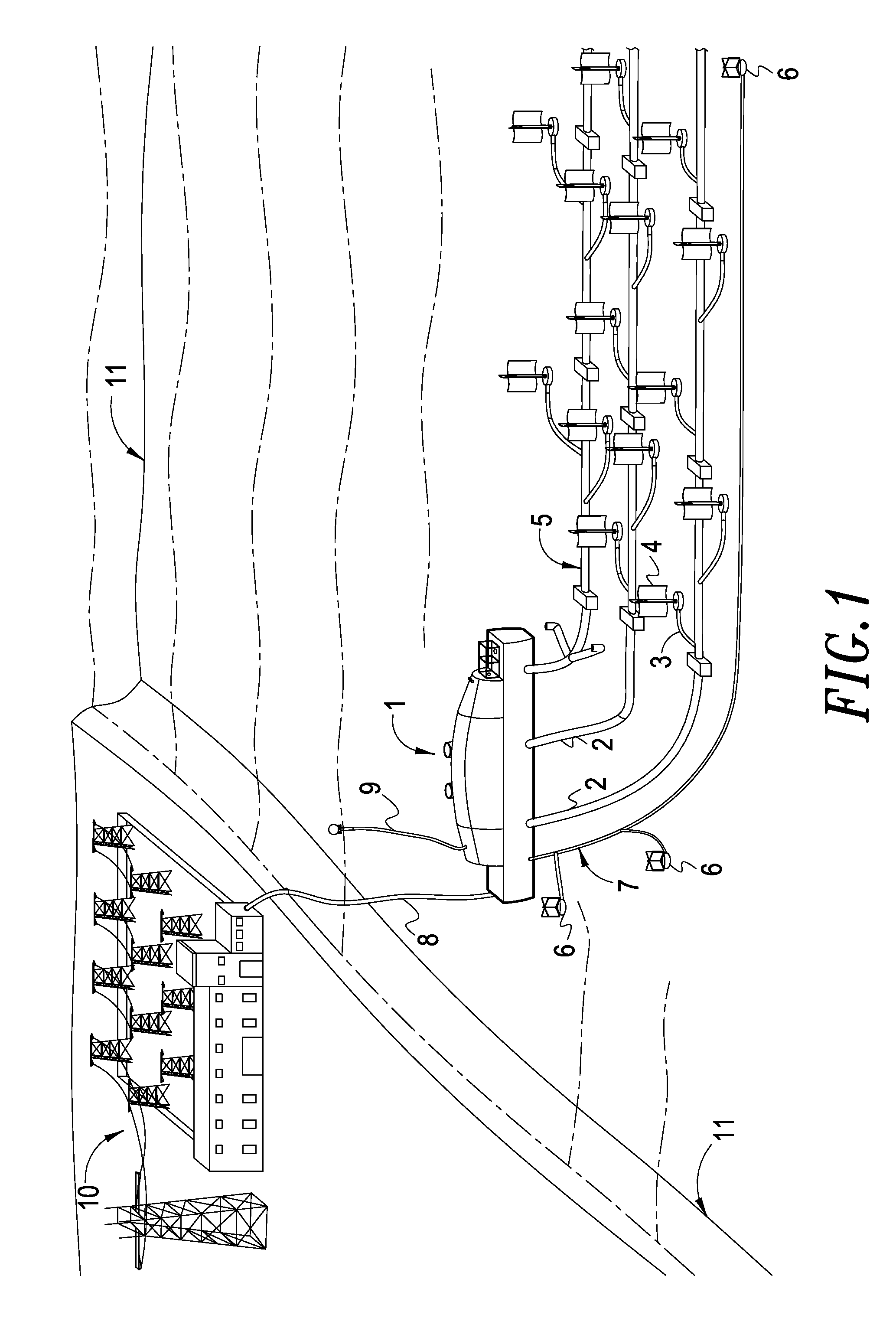
[0024]Please refer to FIG. 1 for a structural view of a sea floor pump tailrace hydraulic generation system in the present invention, wherein the system mainly comprises:

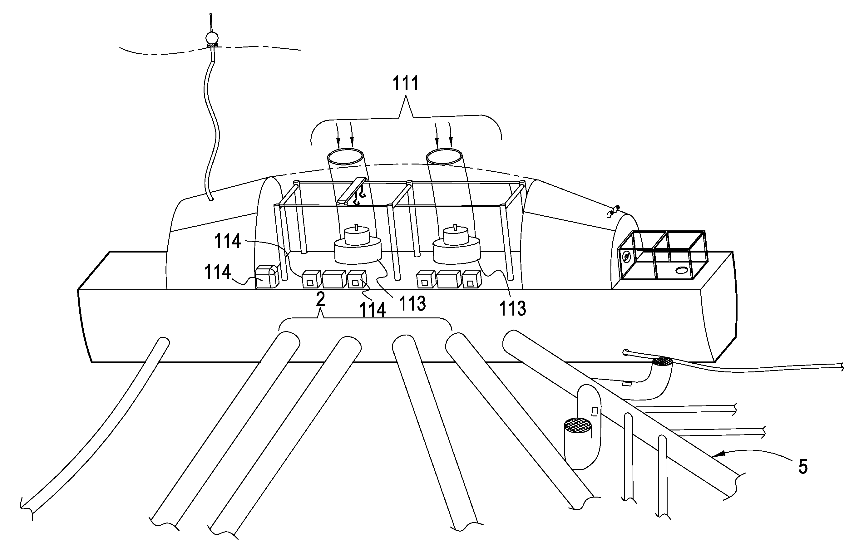
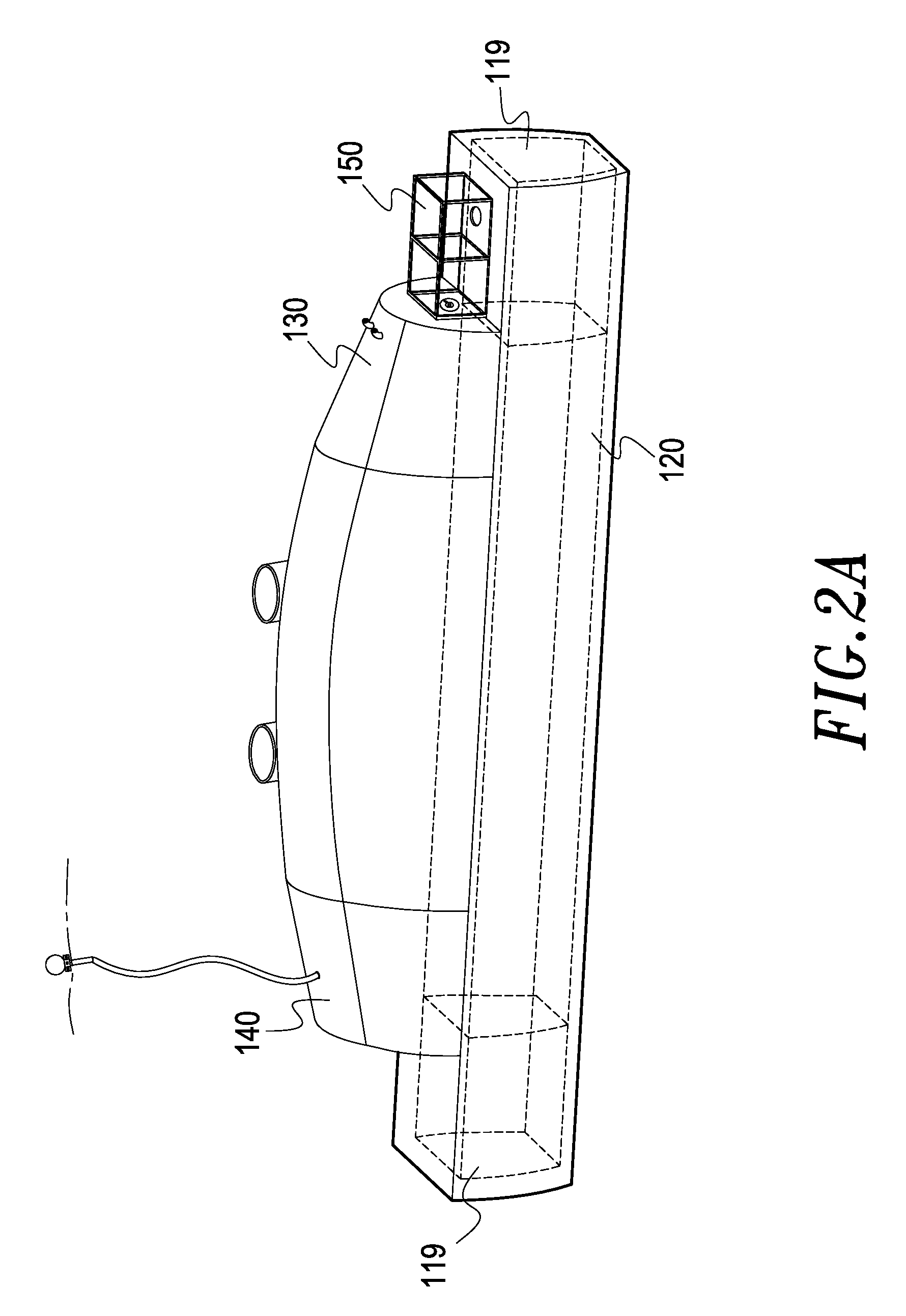
[0025]a sea floor hydraulic generation plant 1, the sea floor hydraulic generation plant 1 is a small to medium size generation plant with its submarine-shaped hull made of rigid steel, the sea floor hydraulic generation plant 1 is placed on the sea floor 11 of the depth between 20 meters and 40 meters, or the sea floor 11 of the depth between 40 meters and 70 meters; the sea floor hydraulic generation plant 1 is a permanent power generation apparatus which is designed to use material that can last for more than 60 years, the power output is about 20 MW capacity when it is placed on the sea floor 11 of the depth between 20 meters and 40 meters and 50 MW capacity when it is placed on the sea floor 11 of the depth between 40 meters and 70 meters;

[0026]a tailrace pipe group comprises tailrace main pipes 2, tailrace bra...


PUM


Abstract

A small or medium size hydraulic generation plant with a steel shell is placed on the sea floor of the stronger tidal/ocean current site. It is added an air hose to get the fresh air, and an entrance for the technician entering, at out side, the plant is connected with three tidal speed meters, a sea floor cable, an inland remote supervision and control center and a group of tailrace pipe of which the branch pipes of which the branch pipes are connected with a tidal/ocean turbine pump farm.
In operation, the plant bring in the sea floor water to generate electricity on large scale. The electricity is transmitted to land by the sea floor cable, while the tailrace firstly drops to the tailrace pond and continually flows thru the tailrace pipes to the turbine pump farm, at last, it is pumped out to the sea floor by the tidal/ocean turbine pump farm.

Description

BACKGROUND OF THE INVENTION[0001]1. Field of the Invention[0002]The present invention relates to a sea floor pump tailrace hydraulic generation system in higher tidal / ocean current speed site, and more particularly, to a hydraulic generation system which brings in water at the sea floor to generate power based on its potential and to send the generated power via sea floor cable to the land. While the tailrace is pumped into sea floor by the tidal current pump farm.[0003]2. Description of the Prior Art[0004]Generally there are two ways to use tidal power, one is to build retaining wall, the other is to use turbine, while the former must rely on the topography and the height of the tidemark, it is rarely deployed; the latter relies on turbines with big size and high efficiency, each turbine is equipped with a gear box to drive a small size generator to generate electricity, however, small generators have high costs and short lifetime, it is not available for commercial use on a large ...

Claims


Application Information

Patent Timeline
IPC IPC(8): F03B13/26
CPCF03B13/00Y02E10/28F03B13/26Y02E10/30Y02E10/20
Inventor TENG, CHING-SHIH
Owner TENG CHING SHIH
Why Eureka
Try Eureka