Input devices operable by reflected light

a technology of input devices and reflected light, which is applied in the direction of instruments, cathode-ray tube indicators, computing, etc., can solve the problems of affecting the quality of life of the eyes, so as to reduce the factors of strain and fatigue, increase the speed of data input, and facilitate data input fast and easy

a technology of input devices and reflected light, which is applied in the direction of instruments, cathode-ray tube indicators, computing, etc., can solve the problems of affecting the quality of life of the eyes, so as to reduce the factors of strain and fatigue, increase the speed of data input, and facilitate data input fast and easy

US20100060583A1Inactive Publication Date: 2010-03-11YAN YONG

Image

  • Input devices operable by reflected light
  • Input devices operable by reflected light
  • Input devices operable by reflected light

Examples


Embodiment Construction

[0022]The purpose of this invention is to solve some problems that occurred in the process of reducing my invention of U.S. Pat. No. 6,770,864 to practice, and to improve the reliability, speed of data entry, and ease of use.

[0023]In general, when a reflector is approaching close to a sensor area and recognized by the system, a signal of keyboard or mouse button depressed or cursor movement is sent to the computer. When the reflector raises up or move out of the sensor area to stop the triggering, a button released or cursor movement stop signal is sent to the computer.

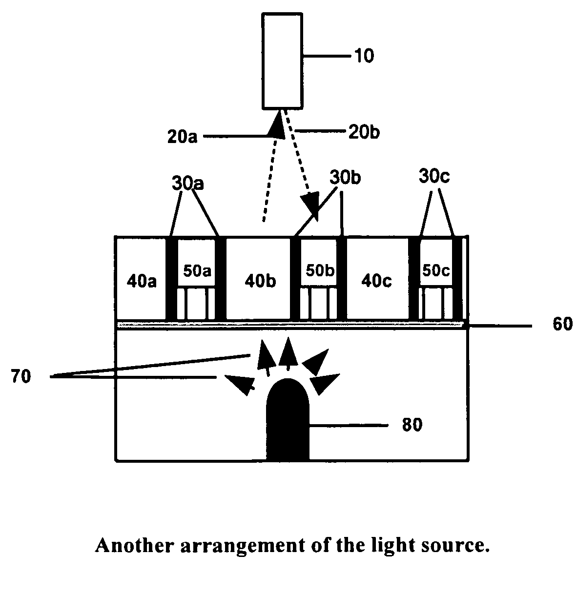
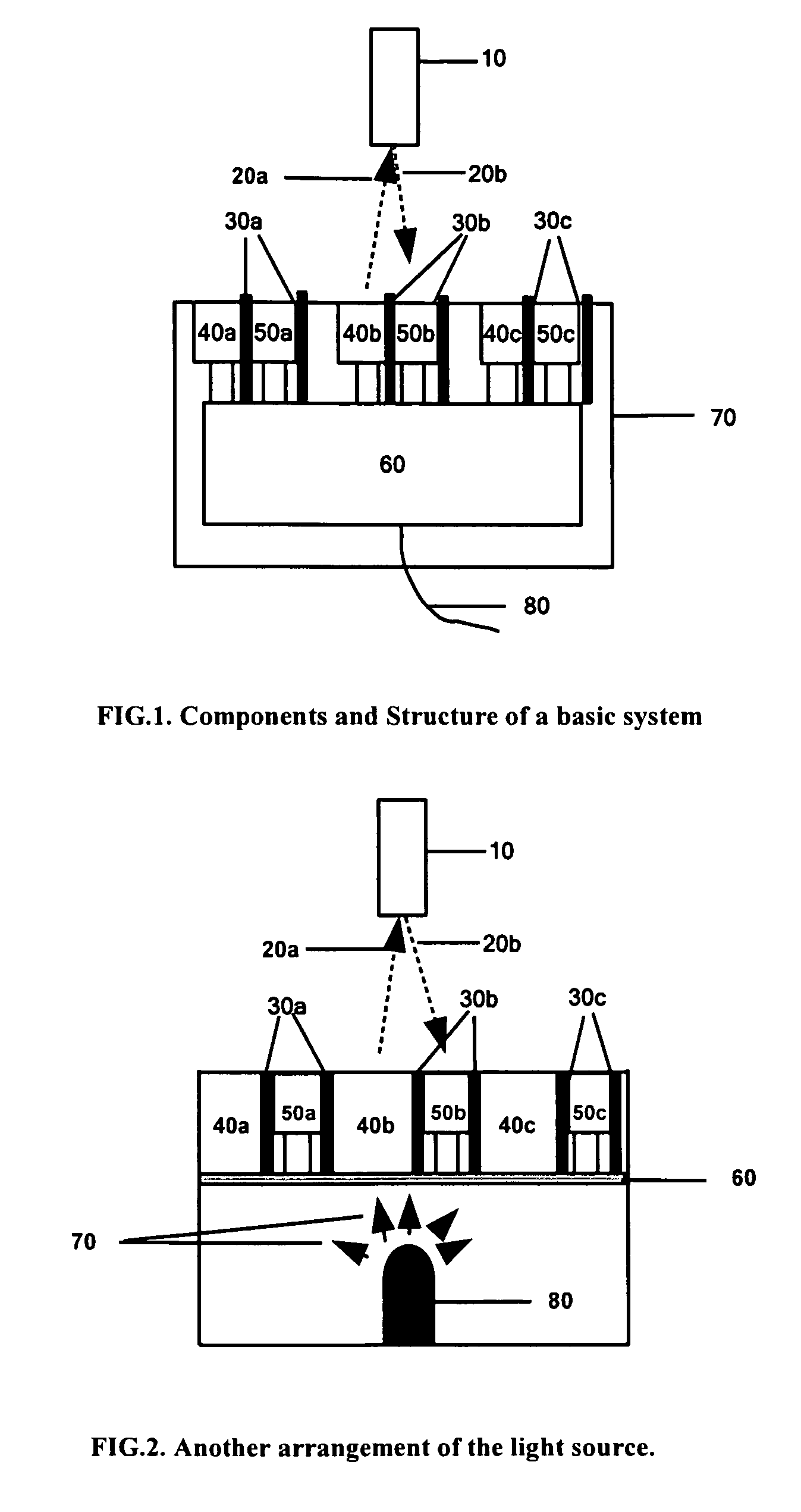
[0024]FIG. 1 shows the essential components and structure of an input device operated by reflected light. Item 10 is a finger or pen style stick with a reflective surface that can reflects light emitted from the device. Item 20a is the light coming out of the device and item 20b is the light being reflected by item 10.

[0025]Items 30a, 30b, and 30c are optical isolating tubes inside which optical sensors 50a, 50b, 50c ...


PUM


Abstract

An optical input apparatus including light sources, light receiving areas, and processing circuits. The light from the sources can be reflected by fingers into the receiving areas where the incident light can trigger electrical signals. The processing circuits can process the signals and transmit corresponding data entry or pointing information to host computer or other electronic systems.The light receiving areas can be arranged and assigned functions to perform keyboard and mouse functions. Additional touch / pressure-triggered switch can be included to assist selection of keys. This invention enables fast and touchless operation of keyboard and mouse that avoid repetitive strain injuries and pains. It also enables fast and more convenient use of small size keyboard.

Description

BACKGROUND OF THE INVENTION[0001]1. Field of the Invention[0002]This invention relates to input devices such as keyboard and pointing devices to computers and other electronic systems such as phones and game machines that use keypad or pointing devices. More specifically, this invention relates to the keypads and pointing devices that can be operated by reflected light.[0003]2. Description of the Related Art[0004]Any discussion of the prior art throughout the specification should in no way be considered as an admission that such prior art is widely known or forms part of common general knowledge in the field.[0005]There have been various attempts to use a beam of light to operate keyboard and pointing devices for computers. U.S. Pat. No. 3,761,877 discloses an optical graphic data tablet operated with a light pen. The position of the light spot on the plate indicated by a digital position indicator determines the signal to be sent to the computer. But its embodiments require the use...

Claims


Application Information

Patent Timeline
11 Mar 2010
Publication
US20100060583A1
IPC
G06F3/033; G06F3/00; G06F3/02
CPC
G06F3/0202; G06F3/0304; H01H2239/022; G06F3/0485; G06F3/04883; G06F3/0421
Inventors
YAN, YONG