Underwater viewing unit for an air mattress

a technology of air mattress and viewing unit, which is applied in the field of underwater viewing unit for air mattress, can solve the problems of low viewing quality, breathing without snorkel, and breathing problems,

Inactive Publication Date: 2010-03-11
KUCHLER MARCUS
View PDF10 Cites 5 Cited by
  • Summary
  • Abstract
  • Description
  • Claims
  • Application Information

AI Technical Summary

Benefits of technology

[0011]Claims 6 to 8 relate to measures suited to mount a transparent pa...

Problems solved by technology

In this case, however, breathing without a snorkel will become a problem because the face is too deeply immersed.
The viewing qualit...

Method used


Image

  • Underwater viewing unit for an air mattress
  • Underwater viewing unit for an air mattress
  • Underwater viewing unit for an air mattress

Examples


Embodiment Construction

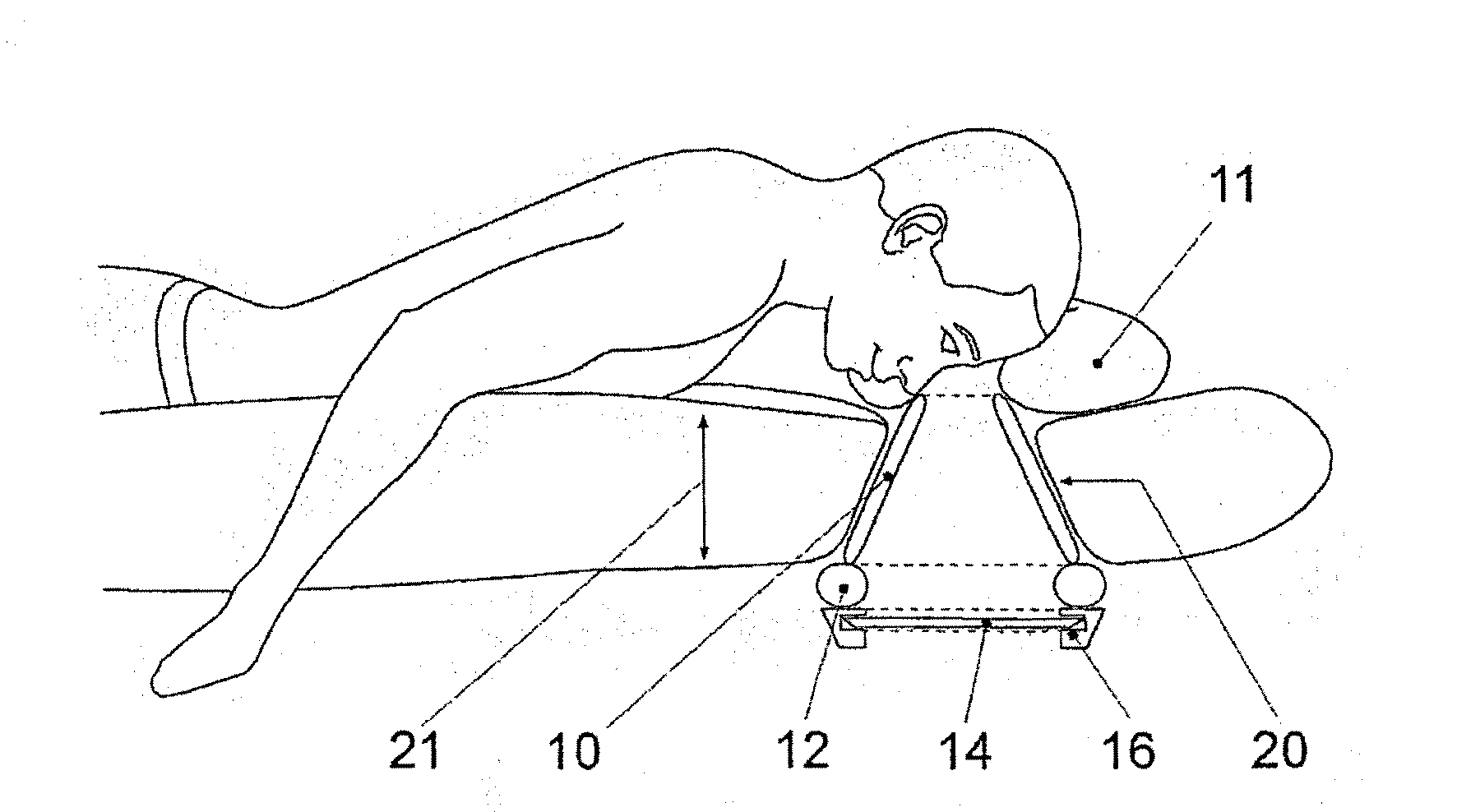
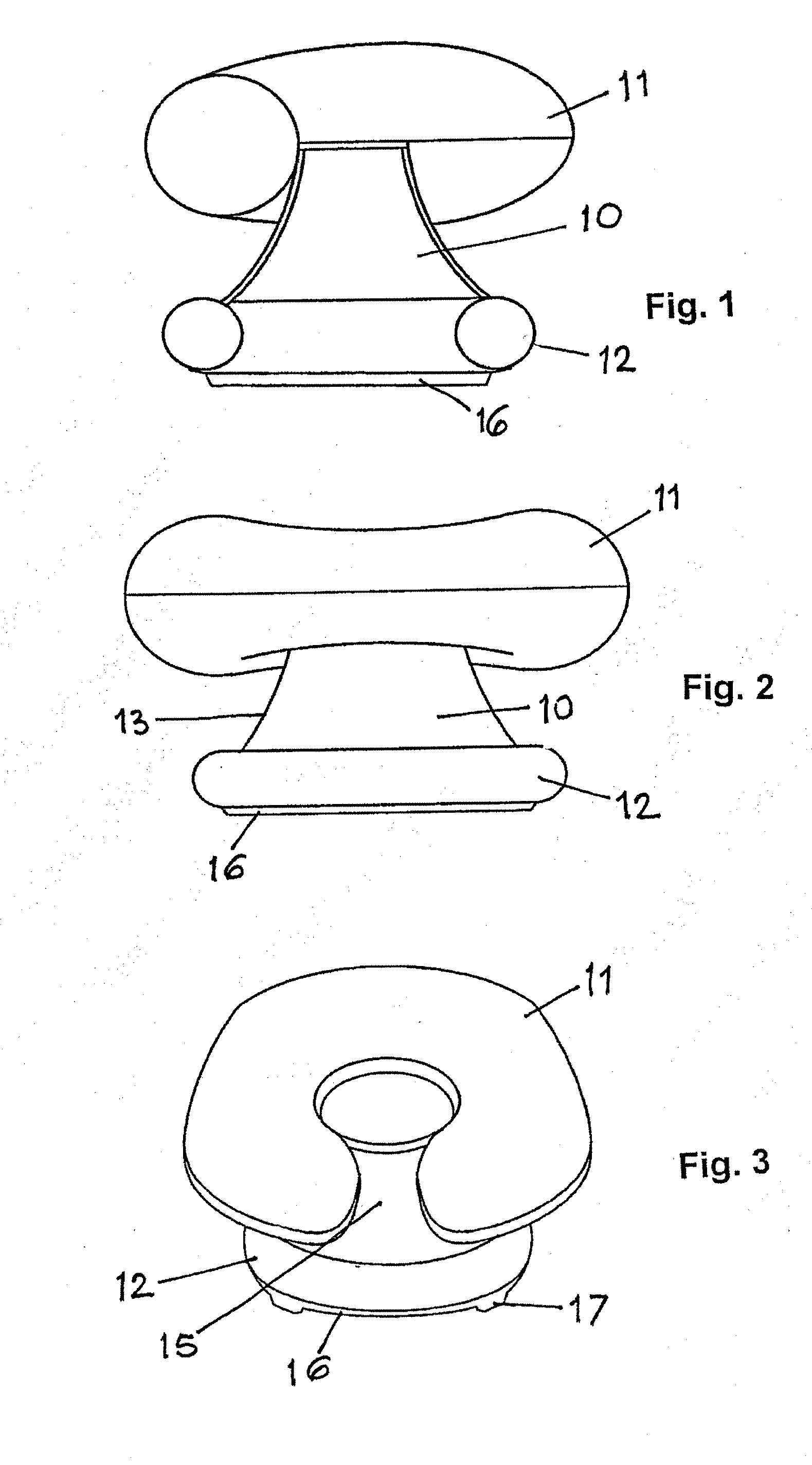
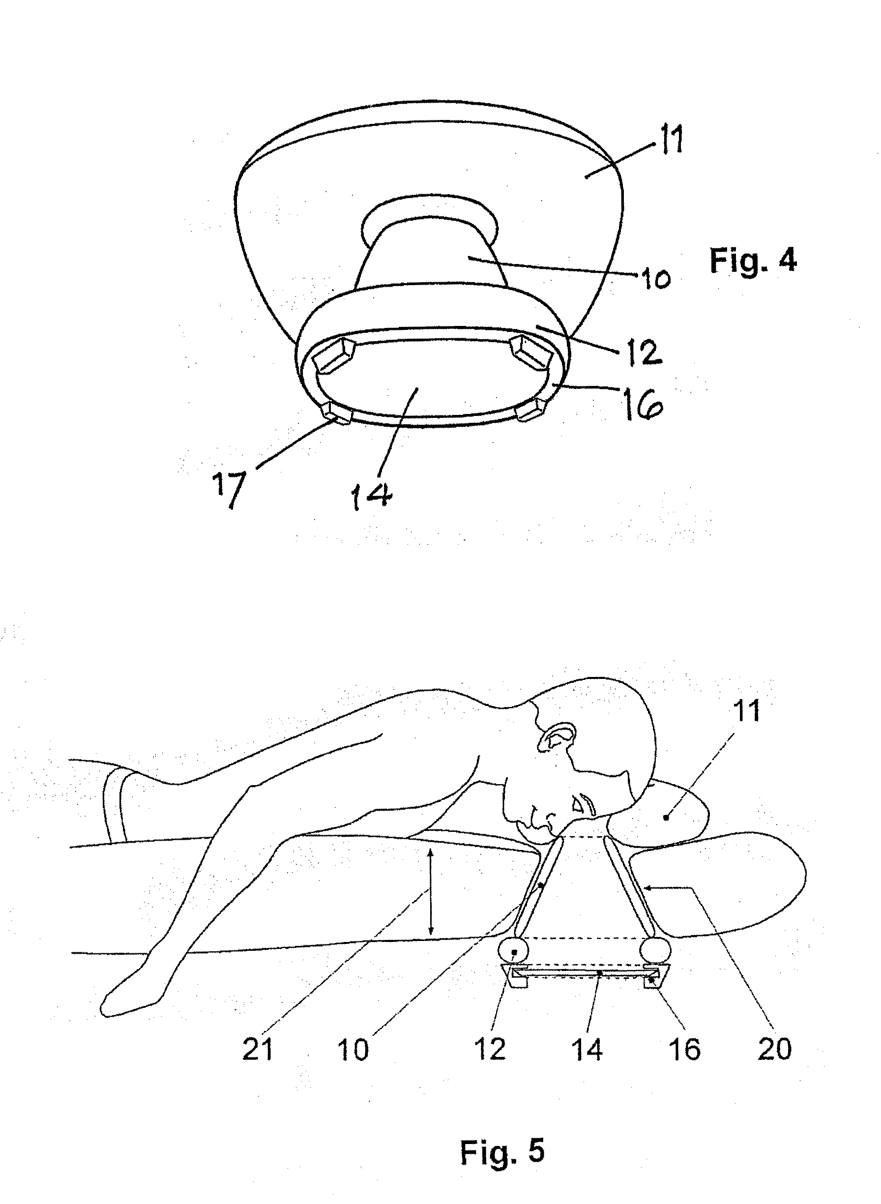
[0018]The underwater viewing unit shown in FIGS. 1 to 4 consist essentially of a generally frusto-conical tube 10, a head rest having the form of an inflatable beaded body 11 connected to the upper rim of the tube, and an inflated beaded ring 12 connected to the lower rim of tube 10. The frusto-conical surface of the tube 10 widens from a smaller viewing opening surrounded by the upper rim, with a concavely curved outer surface 13 toward a larger opening surrounded by the lower rim and closed by a transparent pane 14. In use, the pane 14 is below the water surface.

[0019]While the lower beaded ring 12 is formed as a closed circular or oval torus, the beaded body 11 extends circumferentially over less than 360° to leave free a corresponding circumferential region 15.

[0020]The connections between the tube 10, the beaded body 11 and the beaded ring 12 consist in water-tight welds. The pane 14 has a sharp-edged rim which is clamped into an inward open groove of a frame 16 of elastomeric ...


PUM


Abstract

An underwater viewing unit includes a tube insertable into a through-hole of an air mattress, a rest for the viewer's head provided at the lower end of the tube, and a transparent panedisposed within the tube. The head rest is formed by an inflatable beaded body connected to the upper rim of the tube and extending over less than 360° to leave free a peripheral region outside the tube for free breathing.

Description

PRIOR ART [0001]Snorkels and diving goggles have been used for decades for observing the underwater world. Still, many people know images of fish and corals only from TV or aquarium.[0002]For snorkeling, the person wears diving goggles and a snorkel and floats in the water face-down with or without fins. In this position, the diver is 90% within or under the water. Diving suits and swimming aids reduce the immersion; the face, the ears or the entire head will always remain immersed.[0003]To exercise this kind of diving, the person needs some practice. The diving goggles must be closely fitted to the face to avoid the ingression of water. The head strap must not be too taut or too lose. The snorkel must be in the proper position to reduce the ingression of water. When exhaling, the snorkel must be regularly blown free to keep the inhaled air flow free of water. Persons suffering from claustrophobia cannot wear diving goggles. Persons with sensible ears avoid getting their ears wet. M...

Claims


Application Information

Patent Timeline
IPC IPC(8): B63B35/73A47C27/08B63C11/48B68B1/02
CPCB63C11/49
Inventor KUCHLER, MARCUS
Owner KUCHLER MARCUS
Why Eureka
Try Eureka