Sensors on a Degradation Machine

Inactive Publication Date: 2010-03-11
NOVATEK IP
View PDF5 Cites 29 Cited by
  • Summary
  • Abstract
  • Description
  • Claims
  • Application Information

AI Technical Summary

Benefits of technology

[0011]In another aspect of the invention, a method for reducing wear on a machine for degrading a natural and/or manmade formation has the following steps: providing picks connected to a drum of the machine and at least one accelerometer mounted to the machine; providing electroni

Problems solved by technology

Formation degradation, such as pavement milling, mini

Method used


Image

  • Sensors on a Degradation Machine
  • Sensors on a Degradation Machine
  • Sensors on a Degradation Machine

Examples


Embodiment Construction

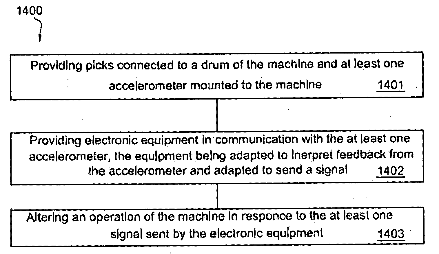
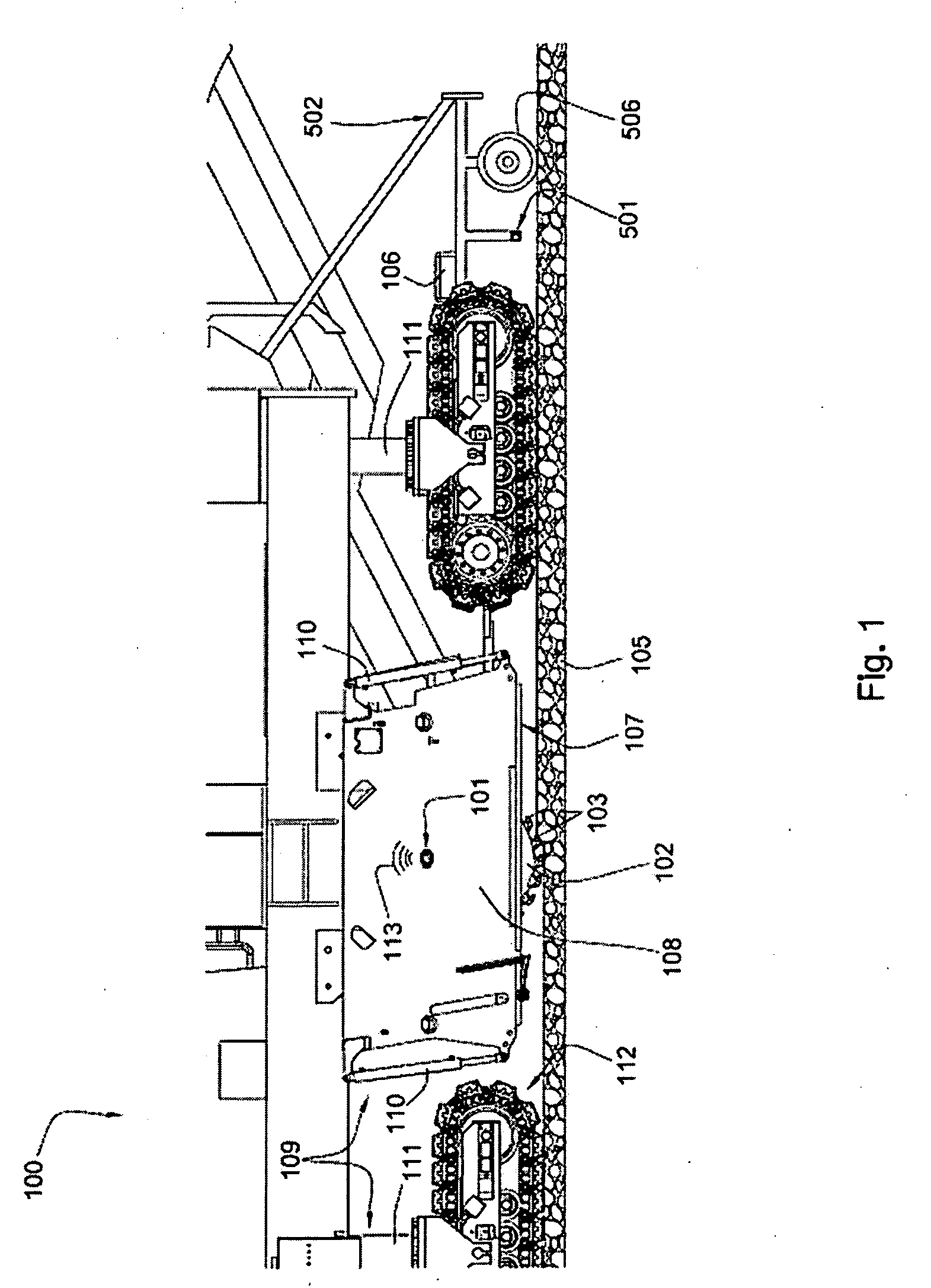
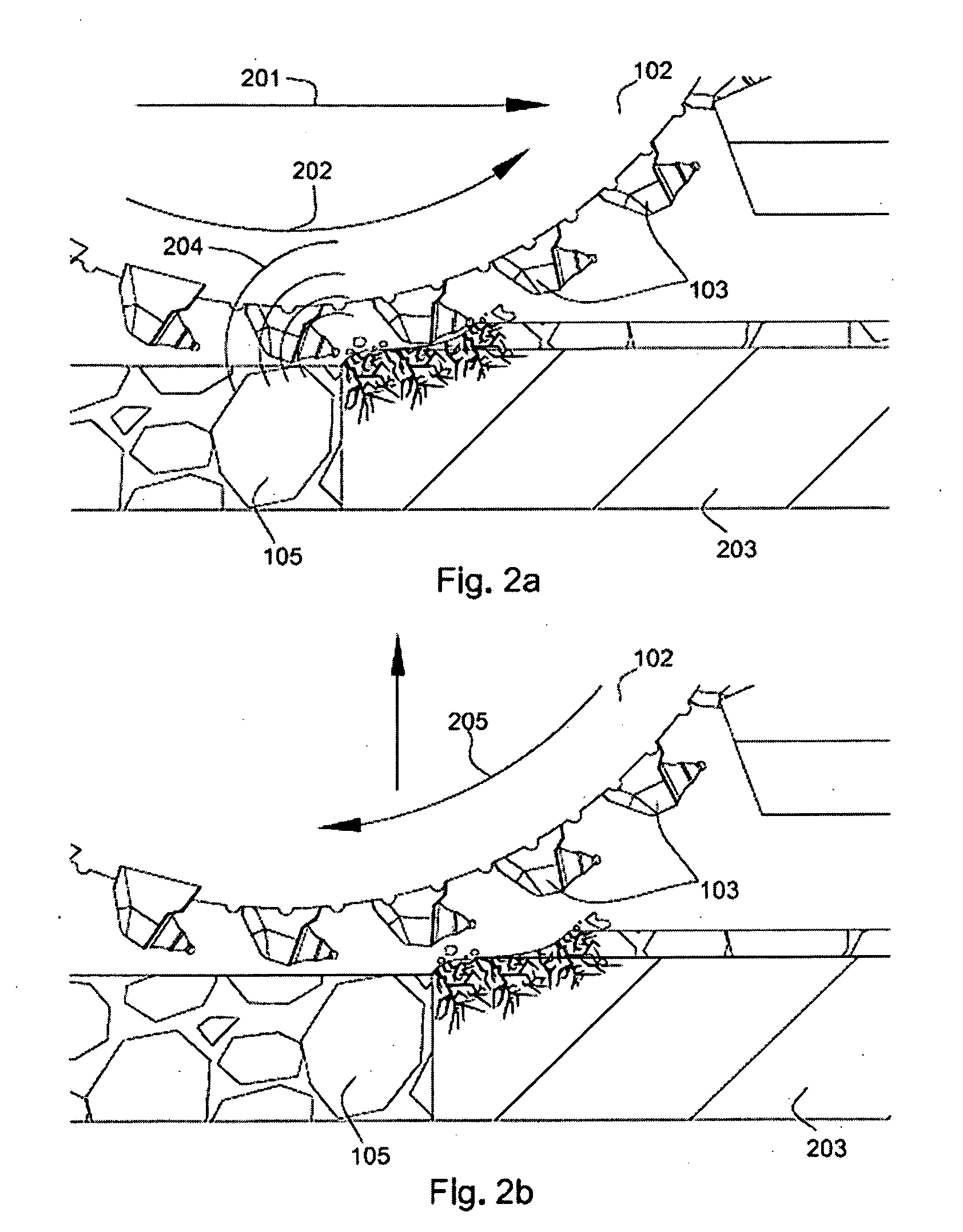
[0030]FIG. 1 is a cross-sectional diagram of an embodiment of a plurality of a high-impact resistant picks 103 attached to a rotating drum 102 connected to the machine 100 adapted to degrade natural and / or manmade formations. In the embodiment of FIG. 1 the machine 100 is a road milling machine 100. The milling machine 100 may be a cold planer used to degrade manmade formations such as pavement 105 prior to the placement of a new layer of pavement. Picks 103 may be attached to the drum 102 bringing the picks 103 into engagement with the formation 105. A holder or block may hold the pick 103 at an angle offset from the direction of rotation, such that the pick 103 engages the pavement 105 at a preferential angle.

[0031]At least one accelerometer 101 is mounted to the machine 100 and is adapted to measure forces acting on the machine 100 in a direction substantially vertical to a direction of travel 201 of the machine 100. The at least one accelerometer 101 may be attached to the outsi...


PUM

PropertyMeasurementUnit
Forceaaaaaaaaaa
Speedaaaaaaaaaa
Elevationaaaaaaaaaa

Abstract

In one aspect of the invention, a machine for degrading a natural and/or manmade formation has picks connected to a drum of the machine and at least one accelerometer mounted to the machine adapted to measure forces acting on the machine. Electronic equipment is in communication with the at least one accelerometer and the electronic equipment has a processor adapted to determine a change in the formation based off of input from the at least one accelerometer. The electronic equipment also is in communication with a mechanism adapted to control, at least in part, a location of the drum.

Description

CROSS REFERENCE TO RELATED APPLICATIONS[0001]This application is a continuation of U.S. patent application Ser. No. 12 / 209,193, which was filed on Sep. 12, 2008 and is herein incorporated by reference for all that it discloses.BACKGROUND OF THE INVENTION[0002]Formation degradation, such as pavement milling, mining, or excavating, may result in wear on attack tools. Consequently, many efforts have been made to extend the life of these tools.[0003]U.S. Pat. No. 5,378,081 to Swisher, Jr., which is herein incorporated by reference for all that it contains discloses a milling machine having a rotary cutter drum which is movable both horizontally and vertically into operating position. The milling machine includes a mobile frame, a cutter rack, a cutter housing, a cutter drum and a pair of cutter skids. The cutter rack is mounted for vertical sliding movement to the front end of the frame. A pair of hydraulic cylinders are provided between the frame and the cutter rack to move the cutter ...

Claims


Application Information

Patent Timeline
IPC IPC(8): G06F19/00
CPCB28D1/18B28D7/005E21C39/00E01C23/088E21C35/24E01C19/00
Inventor HALLWAHLQUIST, DAVIDDAHLGREN, SCOTTMORRIS, THOMAS
Owner NOVATEK IP
Why Eureka
Try Eureka