Piston and method for manufacturing the same

a technology of piston and spherical shell, which is applied in the direction of trunk pistons, machines/engines, plungers, etc., can solve the problems of increasing the deterioration of the yield of the piston, and the increase of the cost of the piston, so as to reduce the weight of the piston, the rigidity of the piston skirt, and the effect of enhancing the rigidity

Active Publication Date: 2010-03-18
HONDA MOTOR CO LTD
View PDF14 Cites 14 Cited by
  • Summary
  • Abstract
  • Description
  • Claims
  • Application Information

AI Technical Summary

Benefits of technology

[0014]According to the second aspect of the invention, the contours of the first and second through holes and the spaces lie on the cylindrical surface of one virtual prismatic body. Consequently, by hole formation using the virtual plasmatic body as a process tool, the first and second through holes and the spaces can be formed by a single process, and the cost can be reduced.
[0015]According to the third aspect of the invention, the contours of the skirt-side ends of the first and second through holes have linear parts. Therefore, while enhancing the rigidity of the piston skirt in the vertical direction, a useless portion in the side walls can be reduced and the weight of the piston can be reduced as compared with the case where the skirt-side end parts have a circular arc shape. Since each of the contours of the pin-boss-side ends has the circular arc shape, although the through holes are in positions close to the pin bosses in the orthogonal direction, deterioration in the rigidity of the pin bosses due to the through holes is prevented.
[0016]According to the fourth aspect of the invention, by the pair of reinforcement ribs extending upward from positions lower than the peripheral part of the piston head in the pin bosses and extending in the pin axis line direction, rigidity of the bosses is enhanced. Moreover, in the case of cooling the piston with coolant, the adhesion area of the coolant in the piston can be increased. Therefore, the performance of cooling the piston can be improved.
[0017]According to the fifth aspect of the invention, as compared with the case where the thickness of the bridge is larger than the thickness of the first side wall and the thickness of the second side wall, the process for forming the upper spaces and the bridges is facilitated.
[0018]According to the sixth aspect of the invention, by forming the upward spaces in the coupling walls formed in the material piston in the process of forming the first and second through holes, the first and second through holes and the upper spaces can be formed by a single process and, further, the bridges can be formed. The cost of the piston can be reduced.
[0019]According to the seventh aspect of the invention, the first and second through holes and the upper spaces can be formed by a single punching process, so that the cost can be reduced.

Problems solved by technology

In the case of forming through holes in side walls coupling pin bosses and a piston skirt and also forming through holes in coupling walls coupling the pair of side walls in order to reduce the weight of the piston, in casting, due to complication in the structure of a casting mold and resulting deterioration in yield increase in the cost of the piston is caused.
Increase in the number of processes causes increase in the cost of the piston.

Method used


Image

  • Piston and method for manufacturing the same
  • Piston and method for manufacturing the same
  • Piston and method for manufacturing the same

Examples


Embodiment Construction

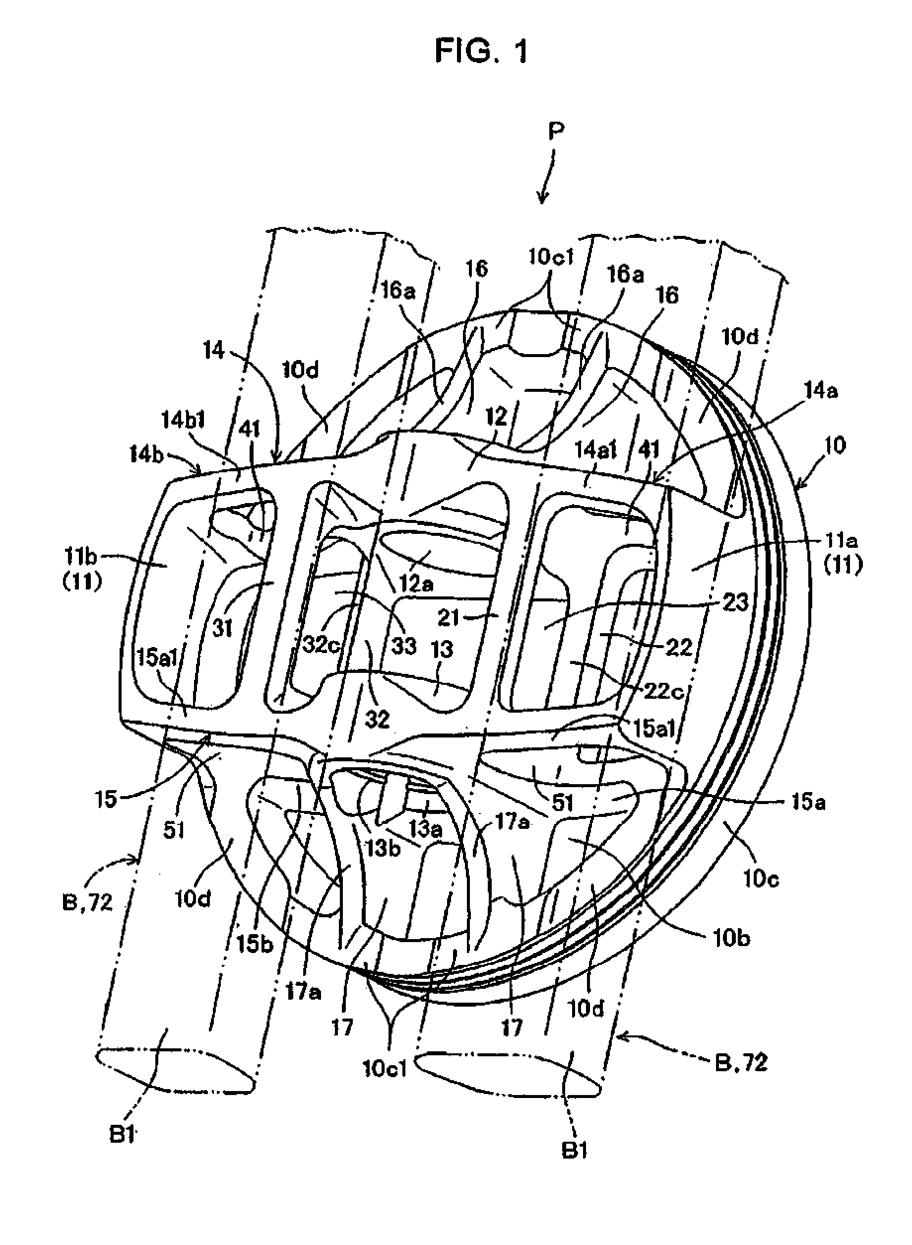
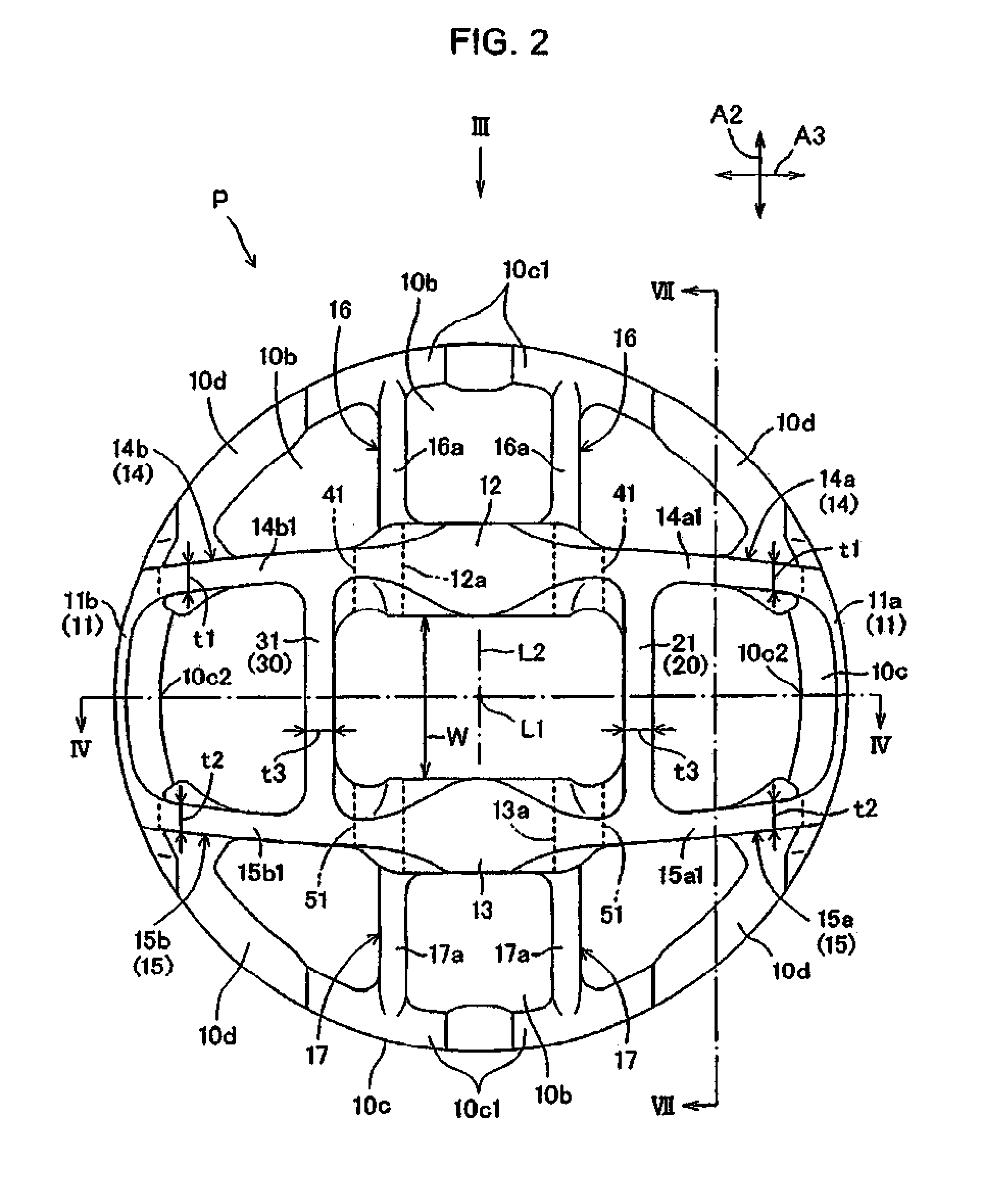
[0030]An embodiment of the present invention will be described below with reference to FIGS. 1 to 9.

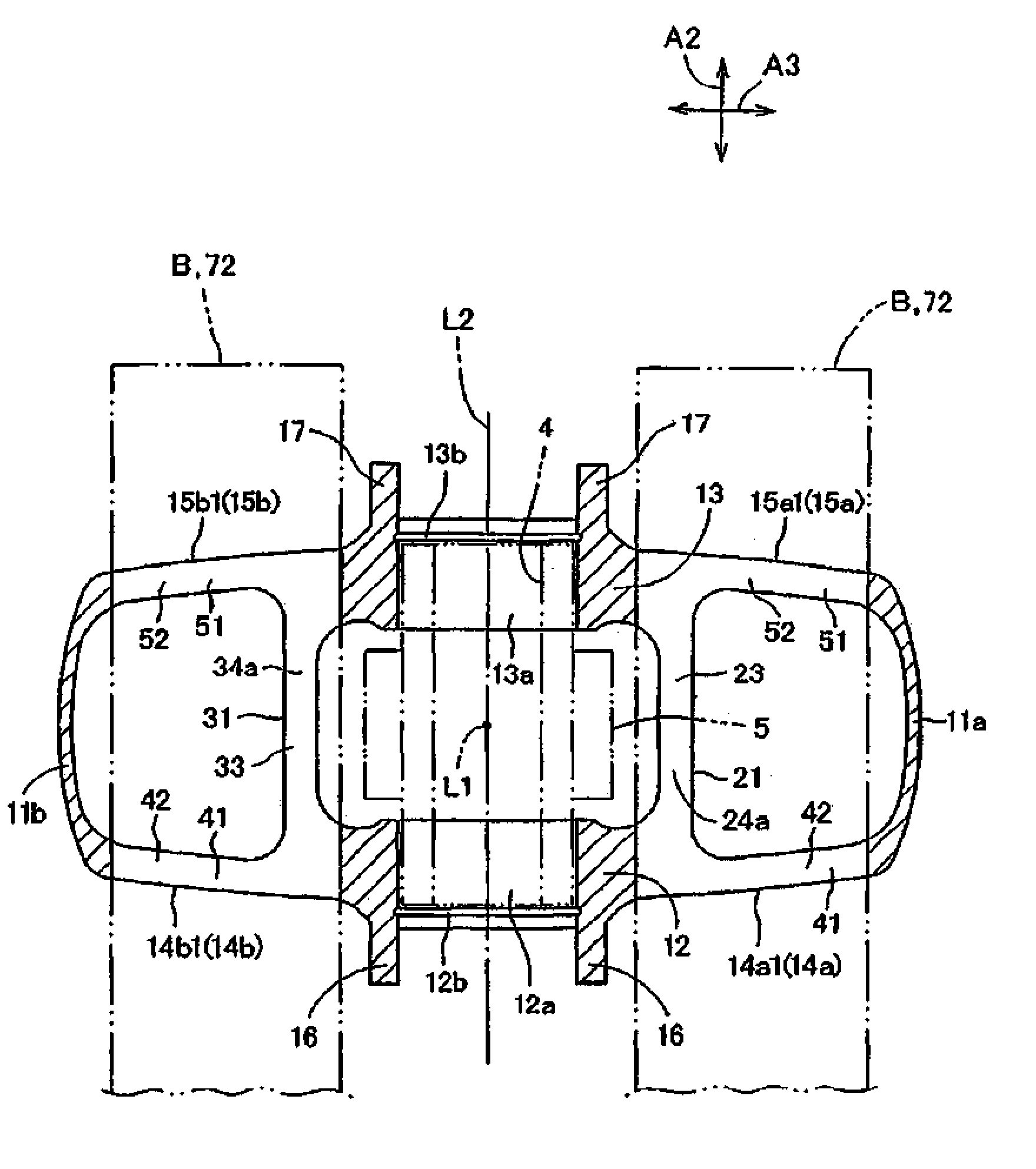
[0031]Referring to FIGS. 1 to 4, a piston P to which the present invention is applied is a piston for an internal combustion engine and is reciprocally fit in a cylinder 1 (refer to FIG. 4) of a four-stroke internal combustion engine. A cylinder head 2 forming the body of the internal combustion engine in cooperation with the cylinder 1 is provided with a combustion chamber 3 so as to face the piston P in a piston axis direction Al parallel with a piston axis line L1 of the piston P. The piston P which reciprocates by being driven by pressure of a combustion gas generated by combustion of air-fuel mixture in the combustion chamber 3 is coupled to the crankshaft of the internal combustion engine via a con rod 5 (also refer to FIG. 5) coupled to the piston P via a piston pin 4 (also refer to FIG. 5), and rotates the crankshaft.

[0032]The piston P includes: a piston head 10 having a top f...


PUM

PropertyMeasurementUnit
thicknessaaaaaaaaaa
rigidityaaaaaaaaaa
weightaaaaaaaaaa

Abstract

The present invention reduces weight while assuring required rigidity of a piston reduces cost of the piston. A piston includes first and second pin bosses supporting a piston pins, a first side wall coupling the first pin boss and a piston skirt, a second side wall coupling the second pin boss and the piston skirt, and a pair of bridges coupling the first and second side walls and forming upward spaces just above. First and second through holes are formed in the first and second side walls. The first and second through holes and the upper spaces are formed by a single punching process using a punch and, simultaneously, the bridges are formed.

Description

TECHNICAL FIELD[0001]The present invention relates to a piston reciprocally fit in a cylinder and a method of manufacturing the piston. The piston is used in, for example, an internal combustion engine.BACKGROUND OF THE INVENTION[0002]A piston for an internal combustion engine is known, having a piston head, a piston skirt, a pair of pin bosses for supporting a piston pin around a pin axis line as a center, and a pair of side walls extending in a direction orthogonal to the pin axis line in plan view and coupling the pin bosses and the piston skirt. In each of the side walls, a through hole penetrating the side wall in the pin axis line direction is formed (refer to, for example, JP-A No. 2000-337212).[0003]Another piston is also known, in which a pair of coupling walls that couple a pair of side walls coupling pin bosses and a piston skirt are formed in positions sandwiching a pin axis line in a direction orthogonal to the pin axis line in plan view in order to enhance rigidity of ...

Claims


Application Information

Patent Timeline
Patent Type & Authority Applications(United States)
IPC IPC(8): F02F3/00F16J1/16
CPCB23P15/10F16J1/16F16J1/001F02F3/0076
Inventor MUKOUHARA, HODAKAMINAMI, KOHJI
Owner HONDA MOTOR CO LTD
Why Eureka
Try Eureka