
Wheel Rim Assembly with Integral Air Cooled Lubricant Cavity and Hub

a technology of air-cooled lubricant and rim, which is applied in the direction of hubs, floating vehicles, vehicle components, etc., can solve the problem that the art does not show the use of the wheel for heat transfer, and achieve the effect of reducing and/or eliminating

Active Publication Date: 2010-03-18
HAMILTON THOMAS S
View PDF18 Cites 11 Cited by
  • Summary
  • Abstract
  • Description
  • Claims
  • Application Information

AI Technical Summary

Benefits of technology

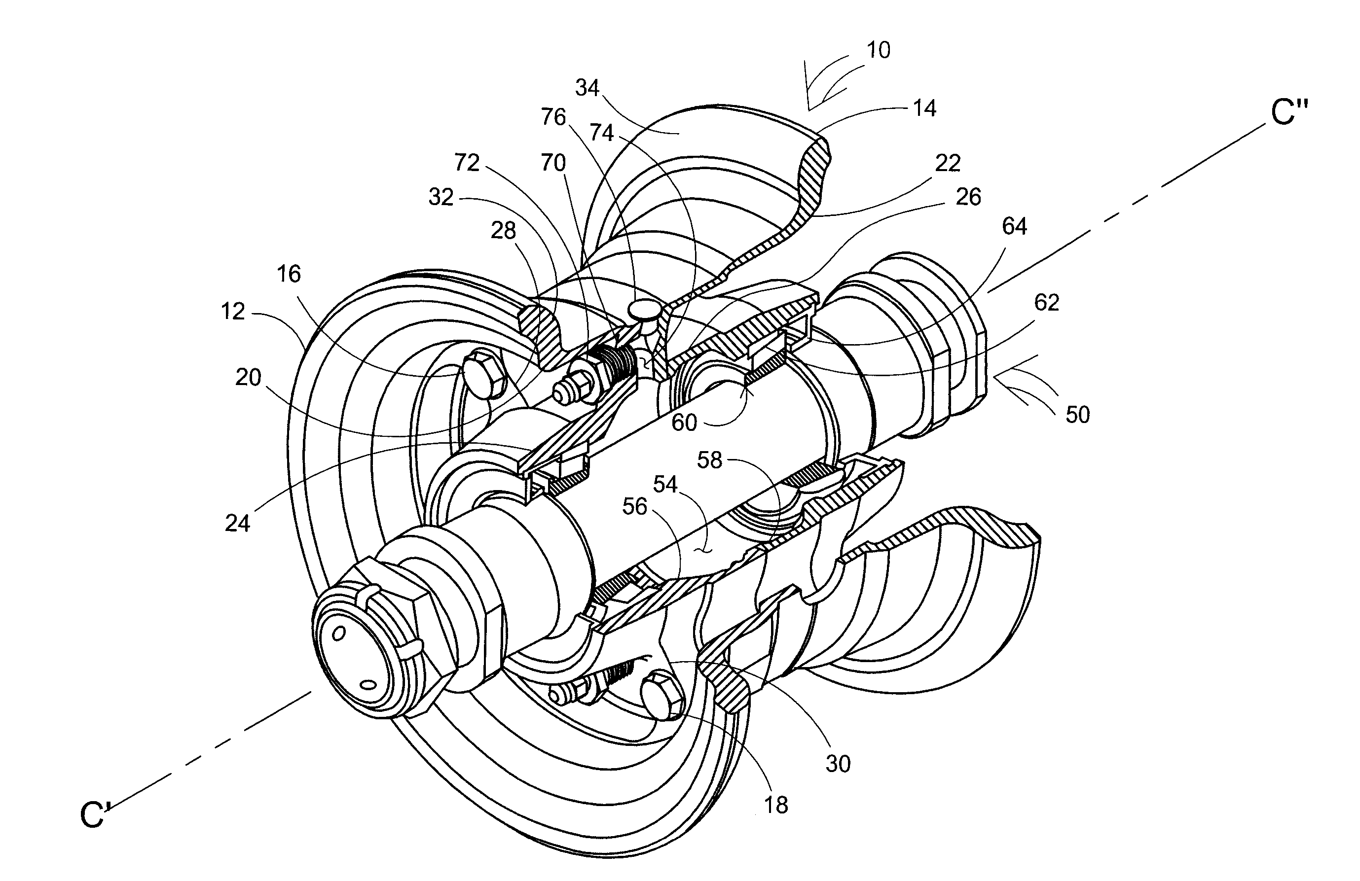
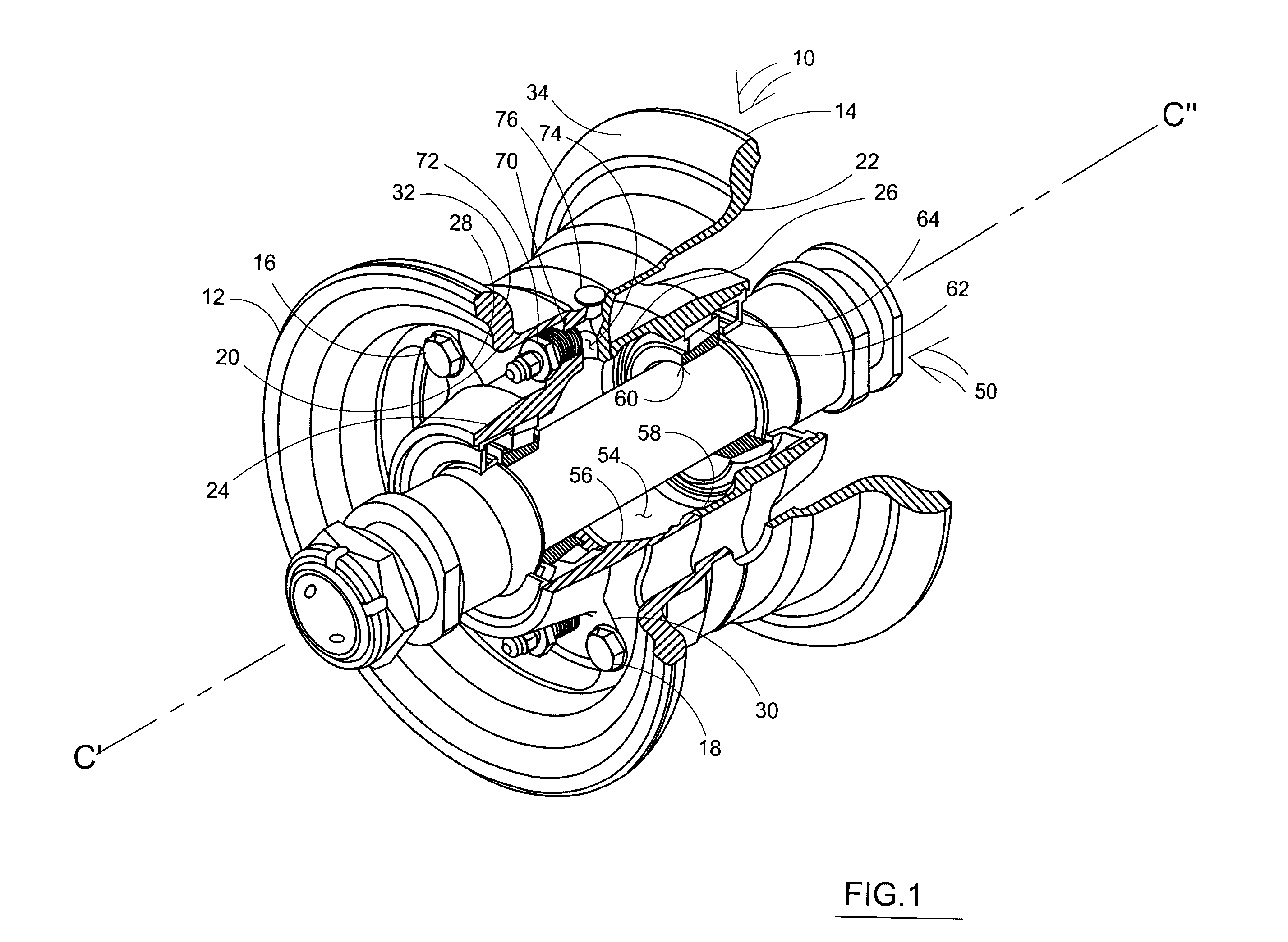
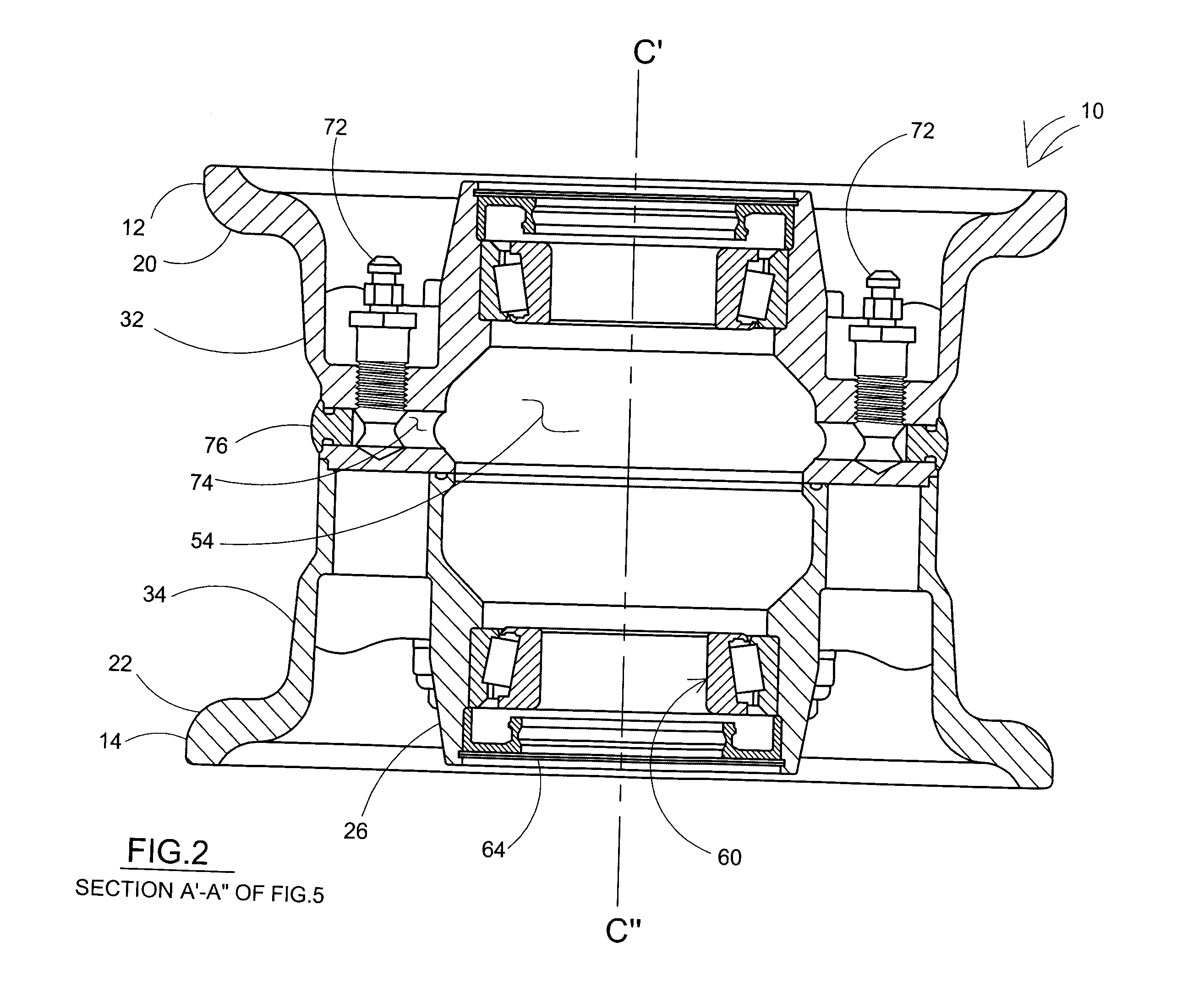
[0014]The invention is an integrated wheel and hub assembly, that utilizes ports located directly on the wheel hub assembly to service the lubricant. This configuration allows for a number of unique advantages including the direct servicing of lubricant while the wheel is still located on a spindle or axle without having to remove the wheel or disassembling the wheel, accessing the lubricant in the hub directly through the ingress and egress ports located in the wheel hub assembly and complete coverage of the internal bearings with lubricant due to the location of the ports being outside of the circumference of the internal bearings.
[0017]This assembly improves on designs that have oil bath reservoirs for lubrication but do not allow heat dissipation through wheel. This assembly improves on oil bath hub assembly designs that have service ports typically mounted to the end of a spindle or axle assembly and require lubricant servicing through the end-mounted ports into the hub assembly, by having the hub internal to the wheel and allowing lubricant servicing through the wheel body. This design improves on wheel designs that are one piece but do not incorporate a liquid for lubrication. This design improves upon grease only hub type wheels which must be removed in order to service wheel axle and bearing lubricant, the invention presented reduces and / or eliminates the need to remove the wheel in order to service wheel axle and bearing lubricant by using the lubricant ingress and egress ports located on the wheel itself.

Problems solved by technology

Further, the prior art does not show the use of the wheel for heat transfer.

Method used


Image

  • Wheel Rim Assembly with Integral Air Cooled Lubricant Cavity and Hub
  • Wheel Rim Assembly with Integral Air Cooled Lubricant Cavity and Hub
  • Wheel Rim Assembly with Integral Air Cooled Lubricant Cavity and Hub

Examples


Embodiment Construction

[0025]The present invention is a wheel rim assembly with integral air cooled lubricant cavity and hub. The rim assembly includes wheel halves with integrated longitudinal air cooled passageways, cooling an integral radially inboard lubricant cavity. The other half wheel hub has an integrated air cooled lubricant cavity. The two wheel halves are sealed into place with an annular peripheral groove located at a radially coextensive position on both wheel halves. An end seal is disposed, at each longitudinal axial end of each wheel half beyond the bearings, in an annular groove. The wheel halves have longitudinal axial openings forming radial voids, between inboard wheel hub walls and outboard wheel hub walls, whose function is to promote air flow and cooling of lubricant cavity. These elements are connected as follows. The first wheel half is attached along a radial plane to the second wheel half with a seal seated between the two wheel halves. An axial end wheel seal caps the axial en...


PUM


Abstract

The two-piece wheel rim assembly includes first and second hub sections affixed together and rotatably mounted on an axle by a set of bearings which are longitudinally spaced apart on the axle. The hub sections have radially inboard wall segments and radially outboard segments. The inboard segments form a radial cavity about the axle longitudinally bounded by the bearings. An oil bath substantially fills the radial cavity except for a small thermal expansion air pocket. The thermal expansion air pocket is positioned above the axle and the bearings when the hub-tire combination is in use. The thermal expansion air pocket has a nominal size only sufficient to account for thermal expansion and contraction of the wheel.

Description

[0001]This is a regular patent application based upon and claiming the benefit of provisional patent application Ser. No. 61 / 097,946, filed Sep. 18, 2008, the contents of which is incorporated herein by reference thereto.[0002]The present invention relates to a wheel rim assembly for airplane tires used in connection with amphibious aircraft.BACKGROUND[0003]This invention pertains to wheels, specifically to wheel designs where the hub is an integral part of the wheel.[0004]Historically wheel hub or rim designs utilized in some aircraft landing systems have used a grease lubricant for the hub which requires the user to first remove the entire wheel assembly from the aircraft and further disassemble the wheel itself, in some cases, in order to service the lubricant.[0005]Prior art wheel assemblies using oil bath hub designs show that the lubricant port is located on the end of the axle or spindle and lubricants are serviced either by removing the hub in its entirety or by servicing po...

Claims


Application Information

Patent Timeline
IPC IPC(8): B60B27/02
CPCB60B3/08B60B25/002B64C25/54B60B27/001B60B27/02B60B25/22B60B27/0073
Inventor HAMILTON, THOMAS S.
Owner HAMILTON THOMAS S
Learn More