
Method and System for Monitoring the Condition of Generator End Windings

a technology of end windings and end windings, which is applied in the direction of electric generator control, instruments, optical elements, etc., can solve the problems of severe service reduction, difficult to accurately determine the proportionality factor, and high cost of electric generators

Active Publication Date: 2010-03-18
SIEMENS ENERGY INC
View PDF30 Cites 35 Cited by
  • Summary
  • Abstract
  • Description
  • Claims
  • Application Information

AI Technical Summary

Problems solved by technology

Such an electrical generator represents a very expensive and long-term investment.
Its failure not only endangers the power equipment itself but may also result in very severe service reduction due to the down time associated with repair.
Although the signals from a vibration sensor are proportional to the stress in the material of the stator bar, the proportionality factor may be difficult to accurately determine.

Method used


Image

  • Method and System for Monitoring the Condition of Generator End Windings
  • Method and System for Monitoring the Condition of Generator End Windings
  • Method and System for Monitoring the Condition of Generator End Windings

Examples


Embodiment Construction

[0019]In the following detailed description of the preferred embodiment, reference is made to the accompanying drawings that form a part hereof, and in which is shown by way of illustration, and not by way of limitation, a specific preferred embodiment in which the invention may be practiced. It is to be understood that other embodiments may be utilized and that changes may be made without departing from the spirit and scope of the present invention.

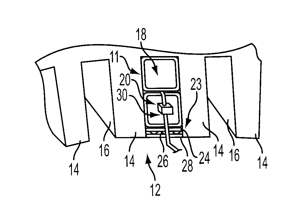
[0020]Referring to FIG. 1, a portion of a stator core winding for an electric generator is illustrated and includes a stator core 12 comprising a plurality of stator teeth 14 defining radially extending slots 16. The stator core 12 comprises stator coils 11 including one or more stator bars located in each slot 16. In the illustrated embodiment, a pair of stator bars, including a bottom stator bar 18 and a top stator bar 20, is located in stacked relation within each slot 16. The stator bars 18, 20 may be wrapped in an insulation layer 2...


PUM


Abstract

A method and system for monitoring the operating conditions of an electric generator. The system includes a triad sensor array formed within a predetermined section of a fiber optic conductor. The triad sensor array is formed of a group of sensors including a first sensor including a Bragg grating for producing a first signal representative of strain in a stator bar of the generator, a second sensor including a Bragg grating for producing a second signal representative of temperature in the stator bar, and a third sensor including a Bragg grating for producing a third signal representative of vibration amplitude in the stator bar.

Description

FIELD OF THE INVENTION[0001]The present invention relates generally to monitoring the condition of electrical machines and, more particularly, to a method and system for monitoring the condition of electrical machines by obtaining multiple measurements through a fiber optic conduit to monitor the condition of an electrical machine.BACKGROUND OF THE INVENTION[0002]An electrical generator used in the field of electrical power generation includes a stator winding having a large number of conductor or stator bars that are pressed into slots in a base body, in particular, a laminated stator core or a rotor body. Such an electrical generator represents a very expensive and long-term investment. Its failure not only endangers the power equipment itself but may also result in very severe service reduction due to the down time associated with repair. To avoid such a condition, increasing use is being made of a diagnostic system for early identification of defects. The diagnostic system furth...

Claims


Application Information

Patent Timeline
IPC IPC(8): H02K11/00
CPCH02K11/0047H02K11/001H02K11/20H02K11/25G01R31/34H02K11/00
Inventor DIATZIKIS, EVANGELOSBRUMMEL, HANS-GERDTWERDOCHLIB, MICHAELINTICHAR, LUTZHUMER, MATTHIASFRERICHS, DETLEF
Owner SIEMENS ENERGY INC
Features
  • Generate Ideas
  • Intellectual Property
  • Life Sciences
  • Materials
  • Tech Scout
  • Unparalleled Data Quality
  • Higher Quality Content
  • 60% Fewer Hallucinations
Learn More