Capacitance change measuring circuit of capacitive sensor device, capacitive sensor module, method of measuring capacitance change of capacitive sensor device, and electronic device

a capacitance change and measuring circuit technology, applied in the direction of resistance/reactance/impedence, instruments, pulse techniques, etc., can solve the problems of time to execute detection operations, capacitance change, and inability to meet high-speed input, so as to reduce the time necessary for detection and reduce the time necessary

Inactive Publication Date: 2010-03-18
SONY CORP
View PDF4 Cites 53 Cited by
  • Summary
  • Abstract
  • Description
  • Claims
  • Application Information

AI Technical Summary

Benefits of technology

[0013]On the other hand, switching control of the analog switches S1, S2, and S3 is executed with about 500 kHz cycle. Thus, until the voltage in point A reaches the reference voltage Vref, approximately 1000 times of switching operations are necessitated. That is, the capacitance change measuring circuit 11 described in JP2002-530680A has the following disadvantage. That is, though its detection precision is high, it takes time to execute detection operation, which means the capacitance change measuring circuit 11 described in JP2002-530680A is not suitable for high speed input.
[0021]In general, the peak level of the detection signal obtained from the first operation region is high, and the peak level of the detection signal obtained from the second operation region is low. Thus, in the second operation region, time for detecting presence of input operation is relatively shorter than that in the first operation region. Therefore, by setting the pulse frequency of the input pulse signal inputted to the second operation region to the higher level, the detection rate is able to be increased.
[0023]Further advantageously, for a first operation region in which the total propagation path length is shorter than a predetermined value, the current amount is set to a first current amount I1, and for a second operation region in which the total propagation path length is longer than the predetermined value, the current amount is set to a second current amount I2 (<I1). That is, it is preferable that the current amount in the operation region in which the peak level is high be set to a higher level. As a result, it becomes possible to reduce time necessary for detection of presence of input operation.
[0024]Therefore, for a third operation region in which the total propagation path length is shorter than a predetermined value, the pulse frequency of the input pulse signal is set to a first pulse frequency F1, and for a fourth operation region in which the total propagation path length is longer than the predetermined value, the pulse frequency of the input pulse signal is set to a second pulse frequency F2 (>F1). That is, by combination with controlling the current amount, it becomes possible to further reduce time necessary for detection of presence of input operation.
[0025]Advantageously, in the capacitance change measuring circuit having the foregoing devices (1) to (5), the reference value of the comparator is set for each of operation regions based on a total propagation path length determined by combination of a first propagation path length on the first and the second electrode patterns and a second propagation path length up to each electrode pattern. In this case, compared to a case that the reference value of the comparator is fixed, the pulse frequency of the input pulse signal inputted to each operation region is able to be speeded up.

Problems solved by technology

That is, though its detection precision is high, it takes time to execute detection operation, which means the capacitance change measuring circuit 11 described in JP2002-530680A is not suitable for high speed input.

Method used


Image

  • Capacitance change measuring circuit of capacitive sensor device, capacitive sensor module, method of measuring capacitance change of capacitive sensor device, and electronic device
  • Capacitance change measuring circuit of capacitive sensor device, capacitive sensor module, method of measuring capacitance change of capacitive sensor device, and electronic device
  • Capacitance change measuring circuit of capacitive sensor device, capacitive sensor module, method of measuring capacitance change of capacitive sensor device, and electronic device

Examples


first embodiment

A. Appearance structure of capacitive sensor module

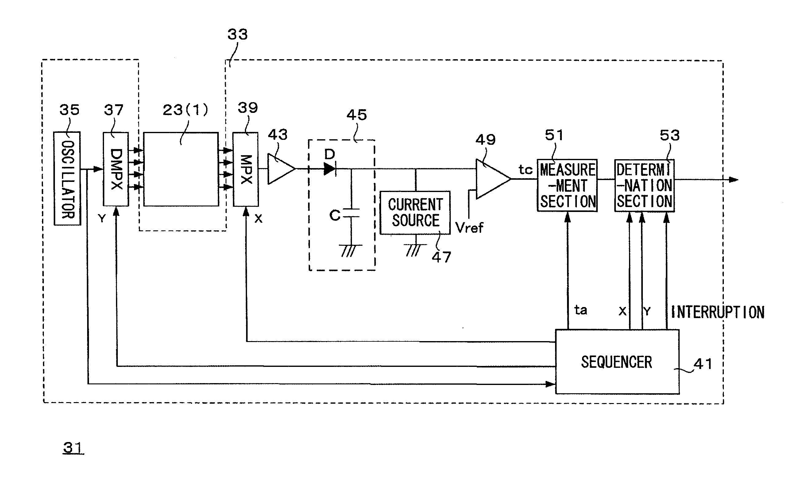
[0123]FIG. 5 illustrates an example of appearance structure of capacitive sensor modules. A capacitive sensor module 21 includes a capacitive sensor device 23, an FPC (flexible printed circuit board) 25 as an extraction wiring thereof, and a capacitance change measuring circuit 27.

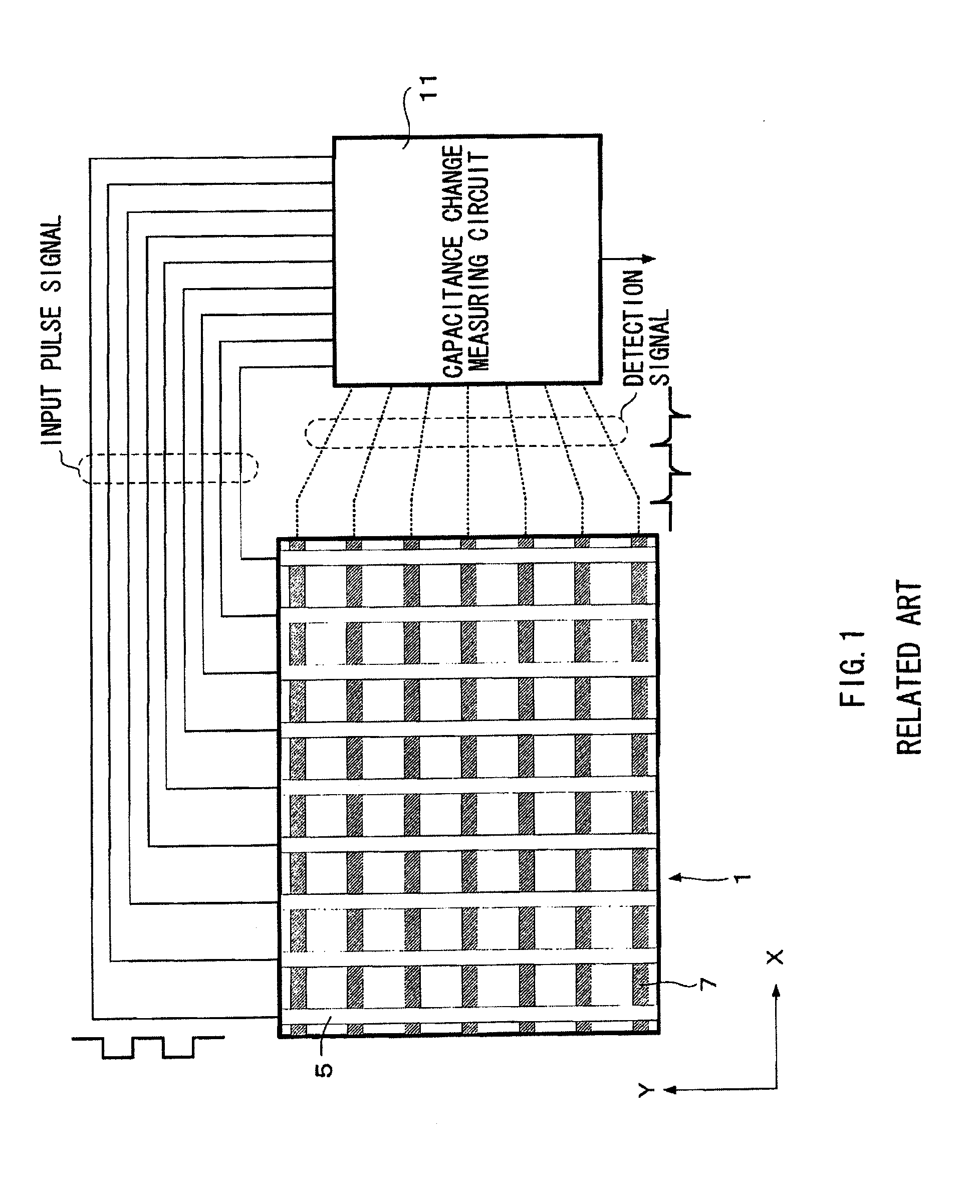
[0124]The capacitive sensor device 23 has a structure in which electrode patterns are formed on the both faces of a base material in a reticular pattern as described above. Further, the capacitance change measuring circuit 27 has a circuit function in which as described above, a closed circuit is line-sequentially selected, an input pulse signal is inputted, and presence of capacitance change is measured based on the detection signal thereof.

[0125]The capacitance change measuring circuit 27 is formed as a semiconductor integrated circuit in some cases, and is formed as a circuit pattern on the FPC in some cases. Further, part of processing of the capacitan...

fifth example

F. Fifth Example

F-1 Detection Principle

[0260]In this example, a description will be hereinafter given of a method of optimizing measurement operation of the elapsed time T according to the position of a measurement point on the operation face (more specifically, a propagation path length).

[0261]However, in this example, a technology for further speeding up the scanning rate by variably controlling the reference potential Vref of the comparator is proposed.

[0262]A description will be given of effect of variably controlling the reference potential Vref of the comparator by using parts (A) and (B) of FIG. 32. FIG. 32 illustrates a relation between the input pulse signal corresponding to the measurement point I and time necessary for determination.

[0263]Part (A) of FIG. 32 illustrates a relation between the input pulse signal and time necessary for discharge of the peak level in the third example. In this case, for determining input operation, reference potential Vref1 corresponding to ...

sixth example

G Sixth Example

G-1. Detection Principle

[0297]In the case of the foregoing examples, the description has been given of the case that the peak level of positive period of the detection signal corresponding to the input pulse signal is detected. That is, the description has been given of the case that the maximum value is detected, and the elapsed time T necessary for discharging thereof is measured.

[0298]The foregoing detection method is also able to be applied to a case that a peak level of negative period corresponding to the input pulse signal is detected. That is, the foregoing detection method is also able to be applied to a case that the minimum value is detected, and the elapsed time T necessary for charging thereof is measured.

[0299]FIG. 38 illustrates processing images. FIG. 38 corresponds to a modified example of the second example. The waveform indicated by a full line in part (A) of FIG. 38 is a detection signal, and the waveform indicated by a dotted line in part (A) of F...


PUM


Abstract

Scanning rate in a capacitance change measuring circuit for a capacitive sensor device is enhanced. The circuit includes: an electrode drive section line-sequentially applying an input pulse signal to a plurality of columns of first electrode patterns in the capacitive sensor device; a peak hold circuit storing a peak level of a detection signal extracted from each column of second electrode patterns into a capacitive element as a corresponding potential; a current source initializing the potential in the capacitive element within one period of the input pulse signal; a comparator comparing the potential in the capacitive element with a reference value; and determination sections each determining whether or not an input operation using a human body or the like is executed, based on a timing information and a reference timing information, the timing information representing a timing when the potential held in the capacitive element crosses the reference value.

Description

BACKGROUND OF THE INVENTION[0001]1. Field of the Invention[0002]The present invention described in the specification relates to a detection technology of input operation or position input to a capacitive sensor device. Particularly, the invention proposed in the specification relates to a capacitance change measuring circuit of a capacitive sensor device, a capacitive sensor module, a method of measuring capacitance change of a capacitive sensor device, and an electronic device.[0003]2. Description of the Related Art[0004]In recent years, various types of position input devices exist. Examples thereof include a sensor device using a finger or an exclusive pointing device having electric characteristics equal to those of a finger. For such a sensor device, various types exist as usage. Discussion will be hereinafter made on a capacitive sensor module which includes a capacitive sensor device and a drive circuit thereof (capacitance change measuring circuit).[0005]FIG. 1 and FIG. 2 il...

Claims


Application Information

Patent Timeline
Patent Type & Authority Applications(United States)
IPC IPC(8): G01R27/26
CPCG06F3/0416G06F3/044H03K2217/960725H03K17/9622H03K2217/960715H03K17/955G06F3/0446G06F3/04166G06F3/0354
Inventor HIRASAKA, HISATONAKAMURA, OSAMUHIROSE, TOSHIYUKIHIROSE, TOSHIHIKOOZAWA, HITOSHIITOU, AKIRA
Owner SONY CORP
Why Eureka
Try Eureka