
Liquid crystal display device and method of manufacturing thereof

Active Publication Date: 2010-03-18
LG DISPLAY CO LTD
View PDF2 Cites 46 Cited by
  • Summary
  • Abstract
  • Description
  • Claims
  • Application Information

AI Technical Summary

Benefits of technology

[0025]An object of the present invention is to reduce the number of processes and facilitate assembling of a liquid crystal display device, wherein a touch panel is provided at a surface of a cover glass.
[0026]Another object of the present invention is to provide a liquid crystal display device, wherein a touch panel is provided at a surface of a cover glass, having minimized structure.
[0027]Another object of the present invention is to provide a liquid crystal display device, wherein a touch panel is provided at a surface of a cover glass, wherein misalignment may be partially prevented when bonding the cover glass and the liquid crystal panel.

Problems solved by technology

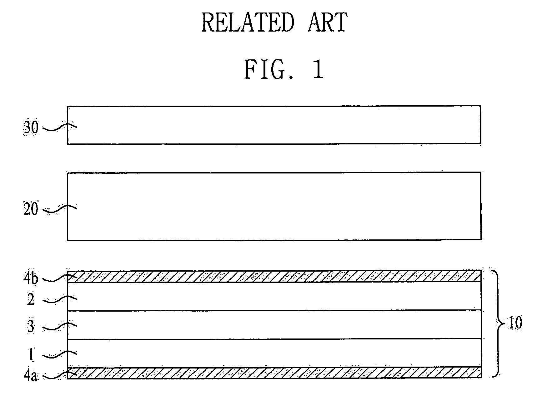
Now, problems of the above-described touch panel attached LCD device will be described.
This inevitably entails additional attachment processes.
Furthermore, since related art touch panels have at least two opposing substrates and two crossing electrodes, it takes many processes to make the related art touch panel attached LCD device.
Further, if the touch panel and liquid crystal panel are misaligned, it is difficult to separate the touch panel attached to the liquid crystal panel because the cover glass is applied after attaching the touch panel to the liquid crystal panel, and forcible separation may damage the touch panel.

Method used


Image

  • Liquid crystal display device and method of manufacturing thereof
  • Liquid crystal display device and method of manufacturing thereof
  • Liquid crystal display device and method of manufacturing thereof

Examples


Embodiment Construction

[0044]Reference will now be made in detail to embodiments of the present invention, example of which are illustrated in the accompanying drawings. Wherever possible, the same reference numbers will be used throughout the drawings to refer to the same or like parts.

[0045]Hereinafter, embodiments of the present invention will be described in detail with reference to the accompanying drawings.

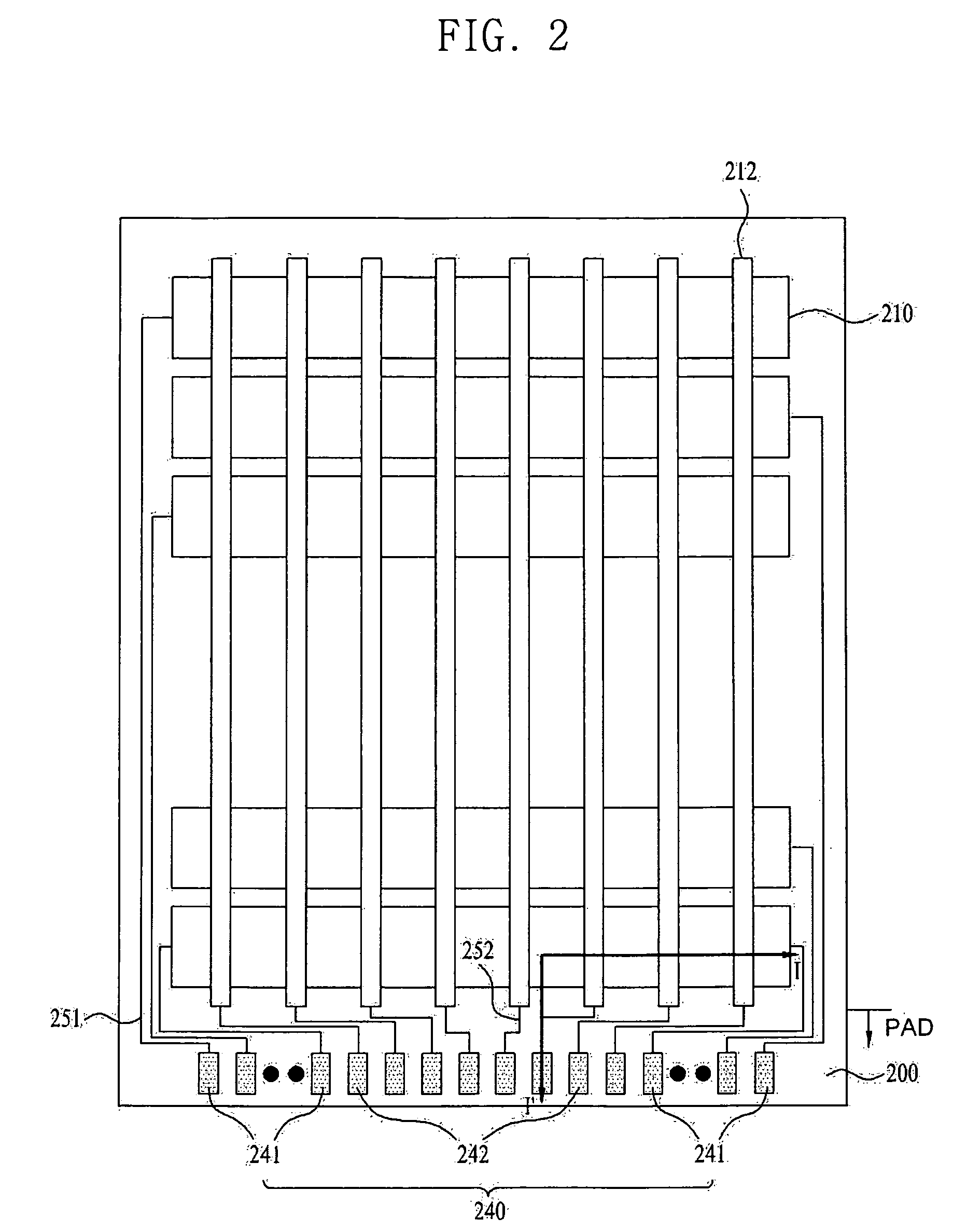
[0046]FIG. 2 is a plan view illustrating the interior of a cover glass provided in a liquid crystal display device. FIG. 3 is a sectional view taken along line I-I′ of FIG. 2, illustrating the a configuration of the liquid crystal display device.

[0047]As shown in FIGS. 2 and 3, the liquid crystal display device includes a cover glass integrated touch sensor 2000 and a liquid crystal panel 100 bonded to each other via an adhesive layer 220. The cover glass integrated touch sensor 2000 includes X electrodes 210 and Y electrodes 212 for touch sensing provided at an inner surface of a cover glass 200 ...


PUM


Abstract

A liquid crystal display device includes: a liquid crystal panel including first and second substrates facing each other and a liquid crystal layer between the first and second substrates, each of the first and second substrates defining a central display region and a peripheral non-display region; a cover glass integrated touch sensor on the liquid crystal panel, the touch sensor including a plurality of transparent first electrodes and second electrodes formed on a surface of the cover glass facing the liquid crystal panel, wherein the first electrodes and second electrodes cross each other; and a touch signal applicator at a side of the cover glass away from the display region of the liquid crystal panel.

Description

[0001]This application claims the benefit of the Korean Patent Application No. P08-090237, filed on Sep. 12, 2008, which is hereby incorporated by reference for all purposes as if fully set forth herein.BACKGROUND OF THE INVENTION[0002]1. Field of the Invention[0003]The present invention relates to a liquid crystal display device, and more particularly, to a liquid crystal display device, wherein a touch panel is provided at a surface of a cover glass.[0004]2. Discussion of the Related Art[0005]Recently, as society becomes increasingly information dependent, a display field, wherein electrical information signals are visually displayed, has been developed rapidly. A variety of flat panel display devices having outstanding performances, such as a thin thickness, light weight and low electricity consumption, have been developed and have rapidly replaced conventional Cathode Ray Tubes (CRTs).[0006]Examples of flat panel display devices include Liquid Crystal Display (LCD), Plasma Panel...

Claims


Application Information

Patent Timeline
IPC IPC(8): G06F3/045
CPCG02F1/13338G02F2201/50G06F2203/04111G06F3/044G02F2202/28G06F3/0443G06F3/0446G02F1/1333G02F1/1343G02F1/1345
Inventor LEE, DEUK SUSONG, IN HYUKPARK, HYUNG SEOK
Owner LG DISPLAY CO LTD
Learn More