Camera and imaging system

Inactive Publication Date: 2010-03-18
SHARP KK
View PDF13 Cites 70 Cited by
  • Summary
  • Abstract
  • Description
  • Claims
  • Application Information

AI Technical Summary

Benefits of technology

[0046]It is thus possible to provide a camera which is capable of providing large depth of field without requiring a moveable lens system. It is not necessary to provide manual or auto focus systems so that moving

Problems solved by technology

The depth of field is such that a fixed focus lens cannot focus on a wide enough range of distances.
Manual systems undesirably require input from the user whereas auto focus systems are expensive and there is a delay whilst such systems focus.
Although this system may be effective, it may be difficult to restore an im

Method used


Image

  • Camera and imaging system
  • Camera and imaging system
  • Camera and imaging system

Examples


embodiment 1

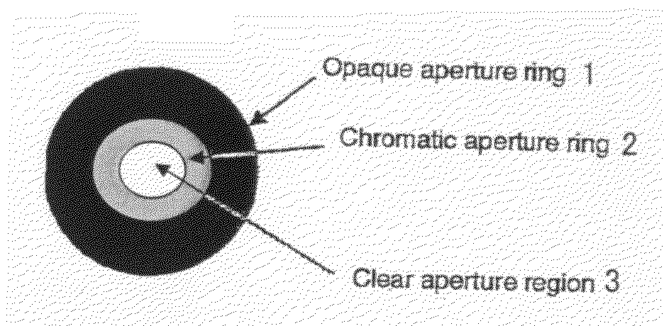
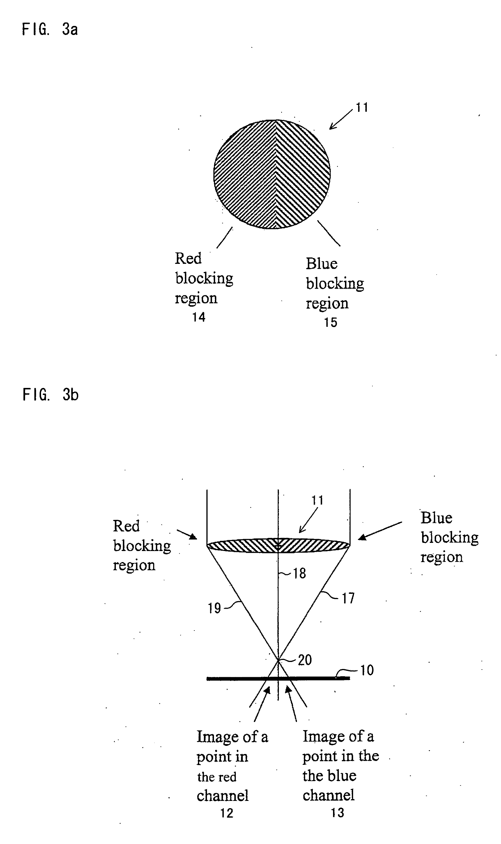
[0088]FIG. 1 is a diagram of embodiment 1. In this embodiment, a chromatic aperture is used to make the aperture of the lens smaller for the blue channel and therefore increase the depth of field in the blue channel. The sharpness of the blue channel is then transposed from the blue channel to the other colour channels by image processing. The gain of the blue channel is increased to compensate for the reduced light input in the blue channel.

[0089]The camera thus has an imaging system with a first depth of field for at least one first frequency of optical radiation, such as at least one first frequency band (blue) and a second smaller depth of field for at least one second frequency of optical radiation, such as at least one second frequency band (red and green).

embodiment 2

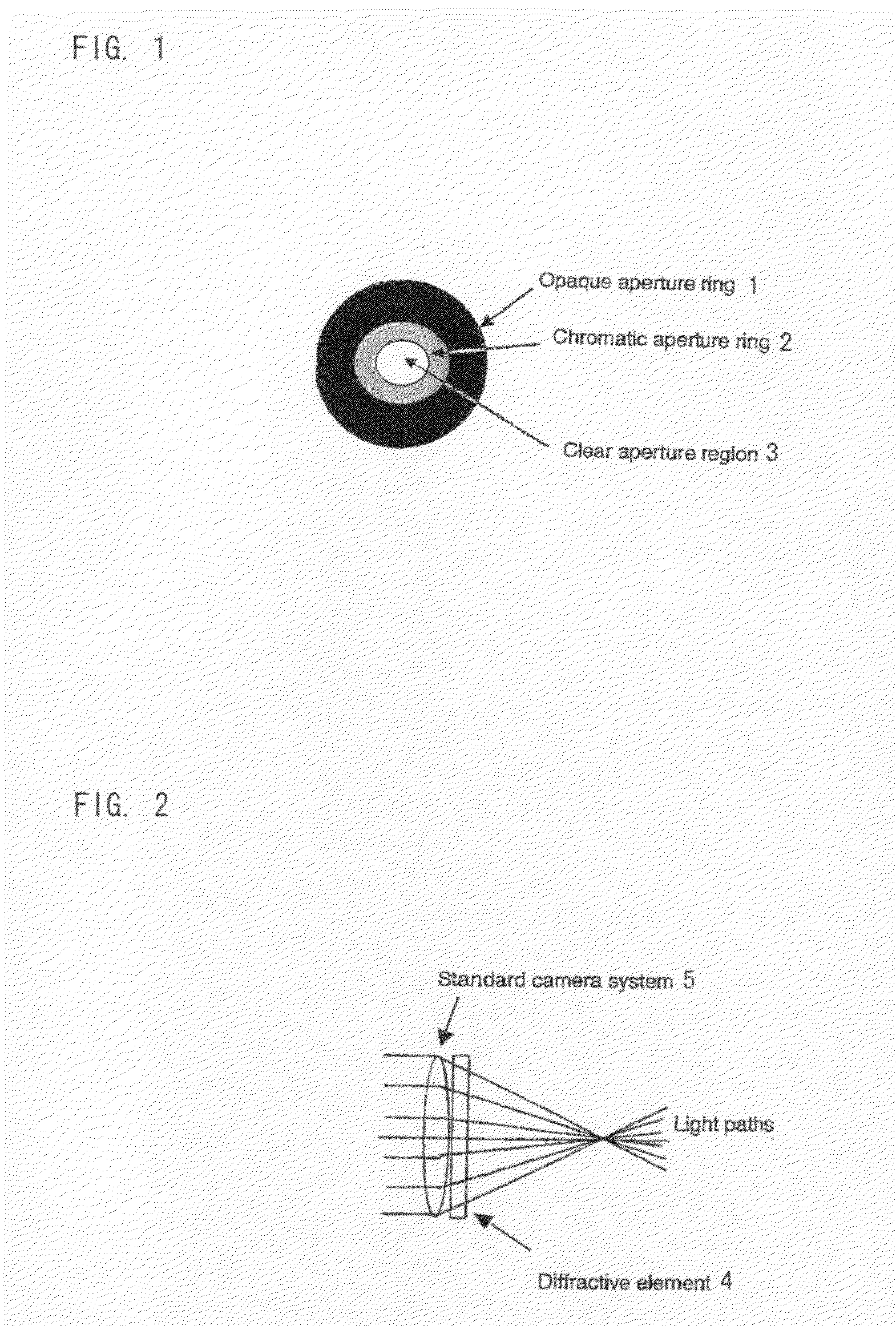
[0090]FIG. 2 is a diagram of embodiment 2. The camera system contains an extra diffractive element 4 that only operates on one colour channel. The diffractive element acts as a wavecoding element and is designed to create a wavecoding effect as known in the prior art. That is to say, the element 4 creates a uniform blur of objects over a wide range of distances such that the blur can be reversed, after the image is recorded, by image processing. The diffractive element 4 may be made to operate for only one colour channel by making it from an amplitude mask that is made from a colour filter material. For example, if a yellow colour filter is used, the diffractive element is substantially invisible to red and green light whilst still effective for blue light.

[0091]In this way, the camera lens operates as a standard lens for red and green channels, thereby giving excellent image quality at medium and far distances because only the blue channel suffers image processing. For the near dis...

embodiment 3

[0092]The technique disclosed in “Image and Depth from a Conventional Camera with a Coded Aperture”, by Levin et al, ACM SIGGRAPH 2007 papers, article No. 70, 2007, discloses a ‘coded aperture’, which is compatible with the concept of having one specific high depth of field colour channel. This paper describes the use of a coded aperture which is an aperture with a special pattern. This pattern blocks certain frequency components of the image in a depth-dependant way. By identifying which frequency components of the image are missing from the image, the distance of an object may be judged and therefore the level of blur from the camera lens may be judged and reversed by image processing. The coded aperture need not be made from black and clear components as stated in the paper, but, in this embodiment, the coded region may be made from a chromatic dye. This would enable the de-blurring to be carried out on one colour channel and, once this sharp colour channel is created, the sharpn...


PUM


Abstract

A camera comprises an imaging system having a first depth of field for one or more first colours and a second depth of field, smaller than the first depth of field, for one or more second colours. The imaging system may comprise an iris with a first aperture for the first colour or colours and a second aperture, which is larger than the first, for the second colour or colours. The first aperture may be defined by an outer opaque ring (1) and the second by an inner chromatic ring (2). The inner ring (2) blocks the first colour(s) and passes the second colour(s). The image formed of the first colour(s) is sharper and its sharpness may be transposed by image processing to the other images.

Description

[0001]This Nonprovisional application claims priority under 35 U.S.C. §119(a) on UK Patent Application No. 0816698.5 filed in the United Kingdom on Sep. 12, 2008, the entire contents of which are hereby incorporated by reference.TECHNICAL FIELD[0002]This invention relates to a camera and to an imaging system.BACKGROUND ART[0003]A few years ago, cameras that were put into mobile phones tended to be small and low resolution. Small cameras can have a very high depth of field (meaning that a wide range of distances may be in focus at the same time). The depth of field was so high that a fixed focus lens could be used and this fixed focus lens was sufficient to focus on all desirable distances.[0004]To increase the performance of today's camera phones, the cameras are larger and of higher resolution. Scaling a camera design to make it larger reduces its depth of field. The depth of field is such that a fixed focus lens cannot focus on a wide enough range of distances. Instead, mechanical...

Claims


Application Information

Patent Timeline
IPC IPC(8): H04N5/228G03B17/00H04N5/335
CPCG02B5/005G02B27/0075H04N9/083H04N5/23293H04N9/045G02B27/58H04N25/611H04N25/11H04N9/03H04N23/10
Inventor MATHER, JONATHANKAY, ANDREWWALTON, HARRY GARTH
Owner SHARP KK
Why Eureka
Try Eureka