Image pickup apparatus and control method thereof
a technology of image pickup and control method, which is applied in the direction of exposure control, instruments, television systems, etc., can solve the problems of deteriorating affecting the effect of exposure, and affecting the quality of picked-up moving images, etc., to achieve the effect of suppressing changes in exposur
- Summary
- Abstract
- Description
- Claims
- Application Information
AI Technical Summary
Benefits of technology
Problems solved by technology
Method used
Image
Examples
first embodiment
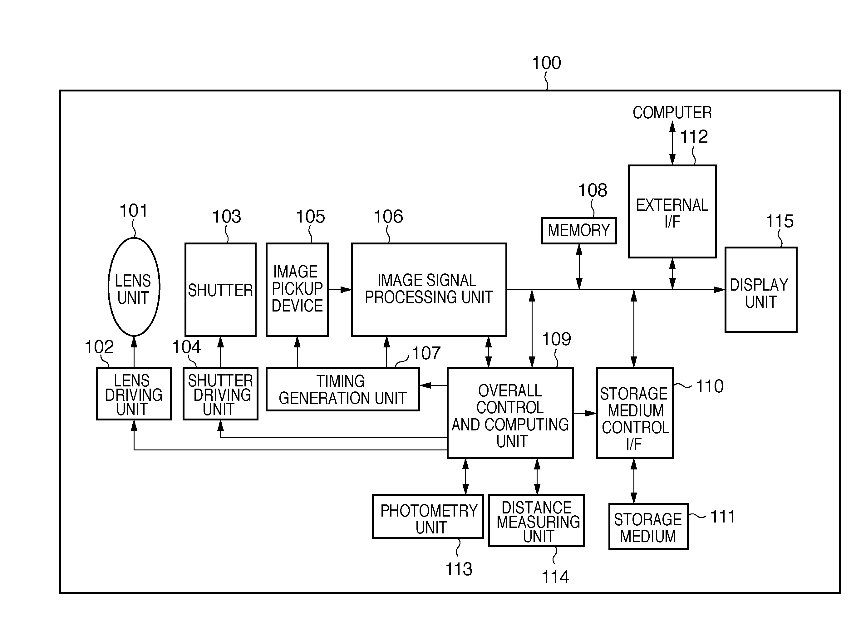
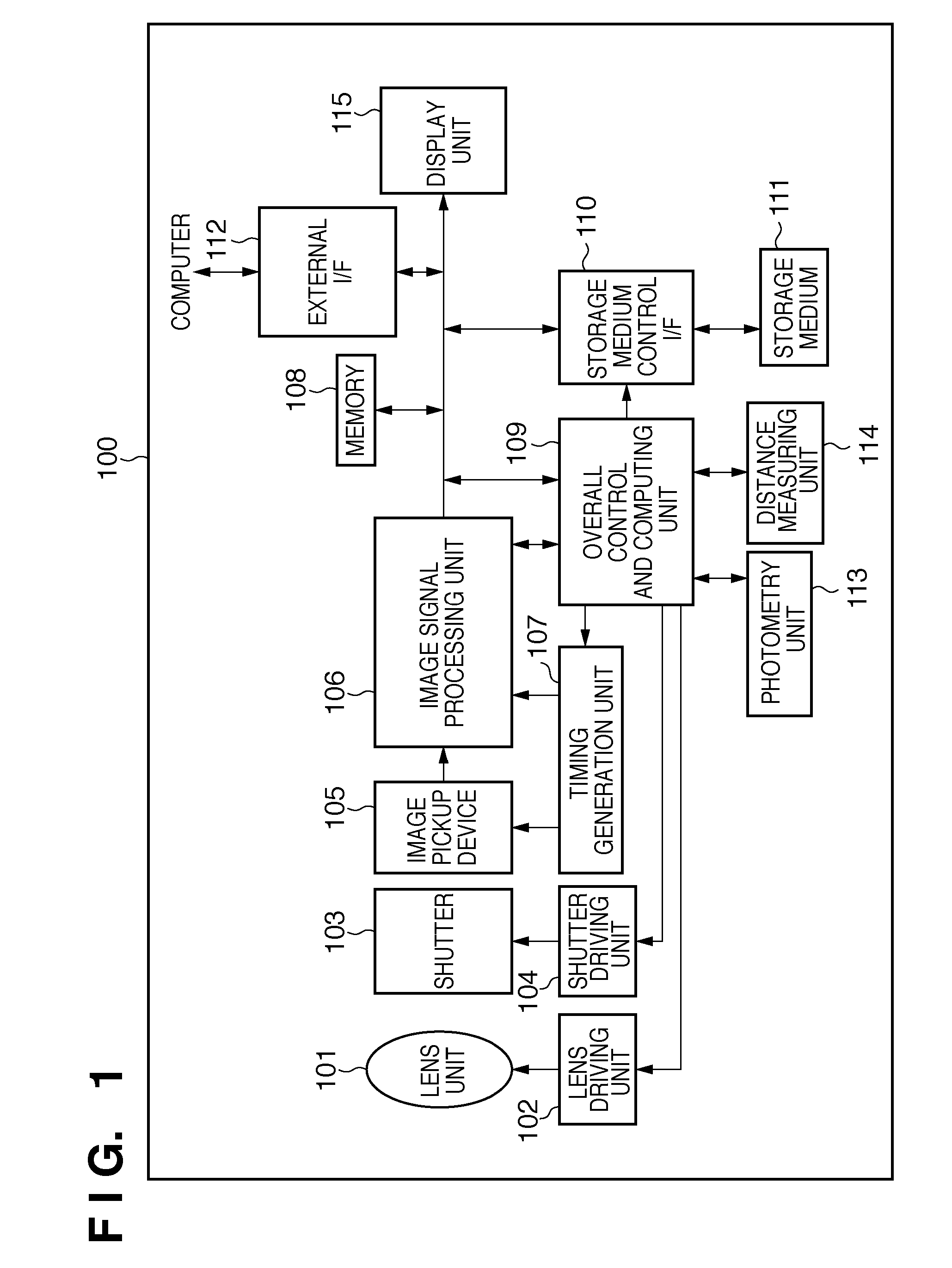
[0033]A first embodiment of the present invention will be explained below with reference to figures. FIG. 1 illustrates an exemplary configuration of a DSLR camera 100 to which the first embodiment of the present invention can be applied. An overall control and computing unit 109 has, for example a CPU, a ROM and a RAM, the CPU operating with the RAM being a work memory according to a program pre-stored in the ROM, thereby controlling the entire DSLR camera 100. The ROM further pre-stores a program diagram for controlling exposure. Additionally, the overall control and computing unit 109, when functioning as correction means, computes image pickup parameters and correction processing coefficient of image data according to the program.
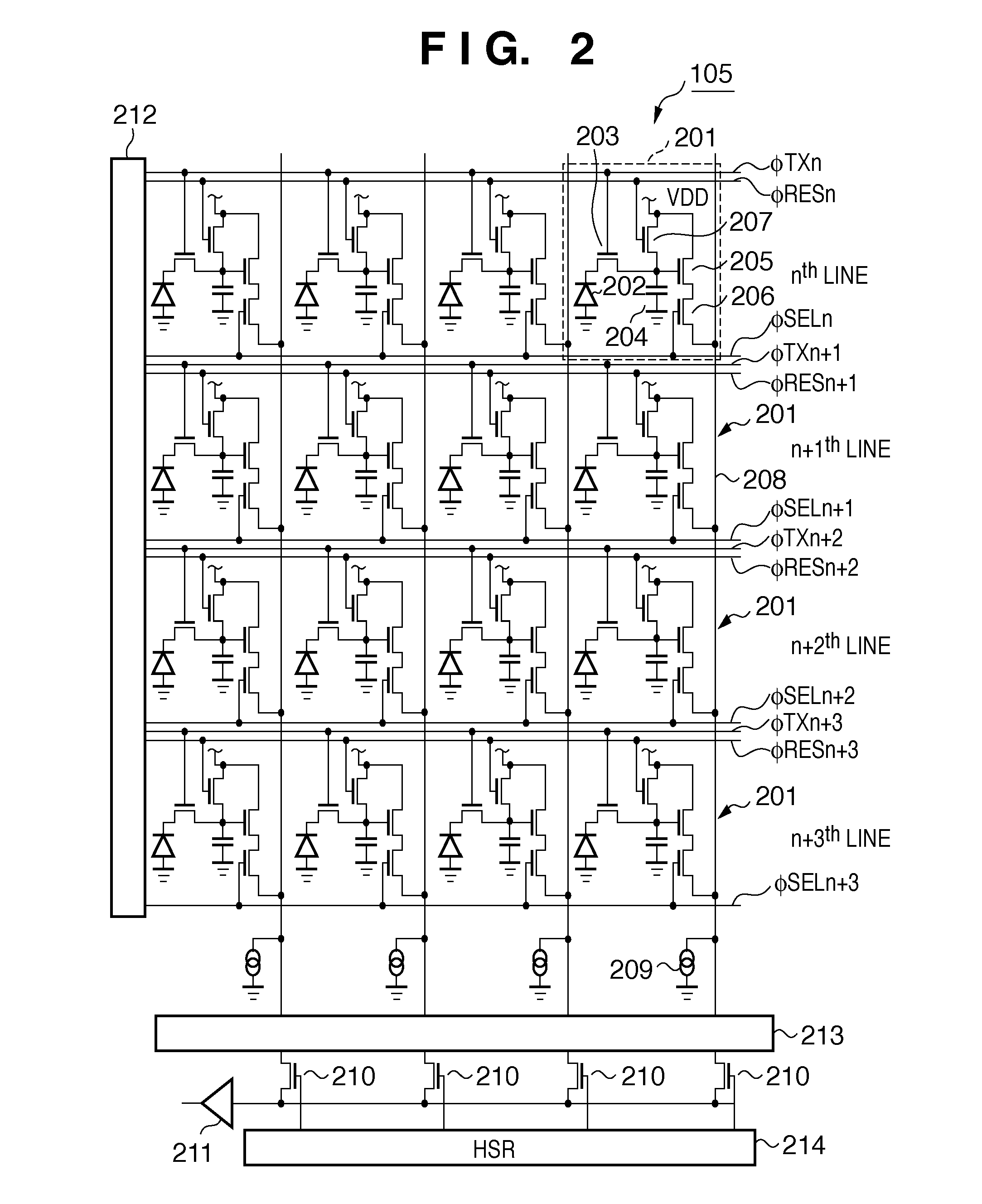
[0034]A lens unit 101 is configured to be exchangeable in relation to the camera body and include an optical aperture mechanism, allowing incoming light to be irradiated onto an image pickup device 105 (to be explained later). A lens driving unit 102, w...
second embodiment
[0075]Next, a second embodiment of the present invention will be explained. Accurate timing for the aperture driving duration can easily be determined in a image pickup apparatus such as a compact digital camera in which the camera body and the lens are integrated into a single unit and are controlled by a common system. On the other hand, in DSLR cameras having interchangeable lenses in which the lens is separated from the camera body and controlled through communication between the camera body and the lens, it is difficult to determine accurate timing for aperture driving duration.
[0076]FIG. 7 shows an exemplary configuration of a DSLR camera 300 according to the second embodiment of the present invention. The DSLR camera 300 according to the present second embodiment, in comparison to the DSLR camera 100 of the first embodiment shown in FIG. 1, has an added vibration detection unit 116 which acts as driving detection means and vibration detection means. Since other parts of the D...
third embodiment
[0086]Next, a third embodiment of the present invention will be explained. In the above-described first embodiment, the correction coefficient B, which is used for correction of inappropriately exposed frames during aperture driving duration, was calculated using average luminance value or accumulated value in certain regions of the frames in concern. In contrast to this, the correction coefficient in the present third embodiment is obtained based on information indicating differences in luminance in vertical directions of images by image signals outputted by the image pickup device 105. The present embodiment calculates the correction coefficient based on projection in horizontal direction of images by image signals outputted by the image pickup device 105.
[0087]In the present third embodiment, the configurations of the DSLR camera 100 and the image pickup device 105, the driving method of the image pickup device 105 and the program diagram can be identical to the above-described f...
PUM
 Abstract
Description
Claims
Application Information
 - R&D
- Intellectual Property
- Life Sciences
- Materials
- Tech Scout
- Unparalleled Data Quality
- Higher Quality Content
- 60% Fewer Hallucinations
Browse by: Latest US Patents, China's latest patents, Technical Efficacy Thesaurus, Application Domain, Technology Topic, Popular Technical Reports.
© 2025 PatSnap. All rights reserved.Legal|Privacy policy|Modern Slavery Act Transparency Statement|Sitemap|About US| Contact US: help@patsnap.com


