
Image forming apparatus

a technology of forming apparatus and forming plate, which is applied in the direction of digital output to print unit, digital marking record carrier, instruments, etc., and can solve the problem of lengthening the reset tim

Active Publication Date: 2010-03-18
RICOH KK
View PDF4 Cites 12 Cited by
  • Summary
  • Abstract
  • Description
  • Claims
  • Application Information

AI Technical Summary

Benefits of technology

[0009]It is an object of the present invention to at least partially solve the problems in the conventional technology.

Problems solved by technology

However, this process lengthens the reset time.

Method used


Image

  • Image forming apparatus
  • Image forming apparatus
  • Image forming apparatus

Examples


Embodiment Construction

[0017]Exemplary embodiments of the present invention are described in detail below with reference to the accompanying drawings. An image forming apparatus according to an embodiment of the present invention is a multifunction peripheral (MFP) having various functions as a copier, a facsimile machine, and a printer. However, some other image forming apparatuses can be used, instead.

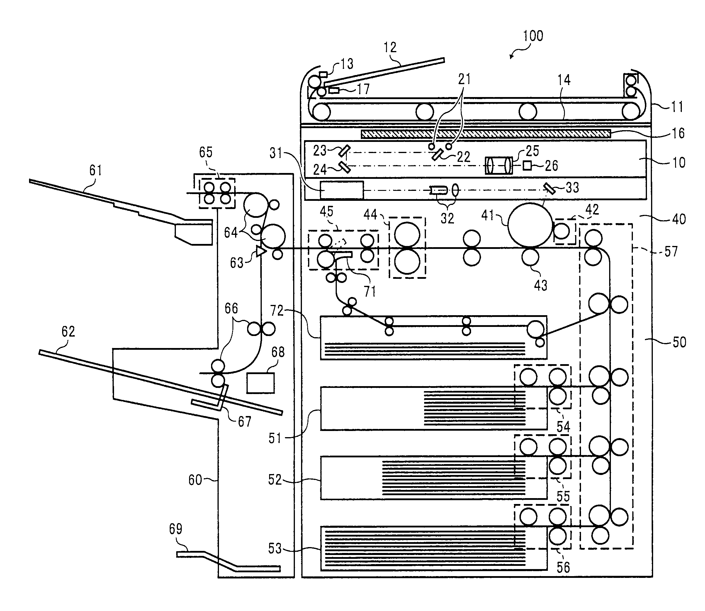
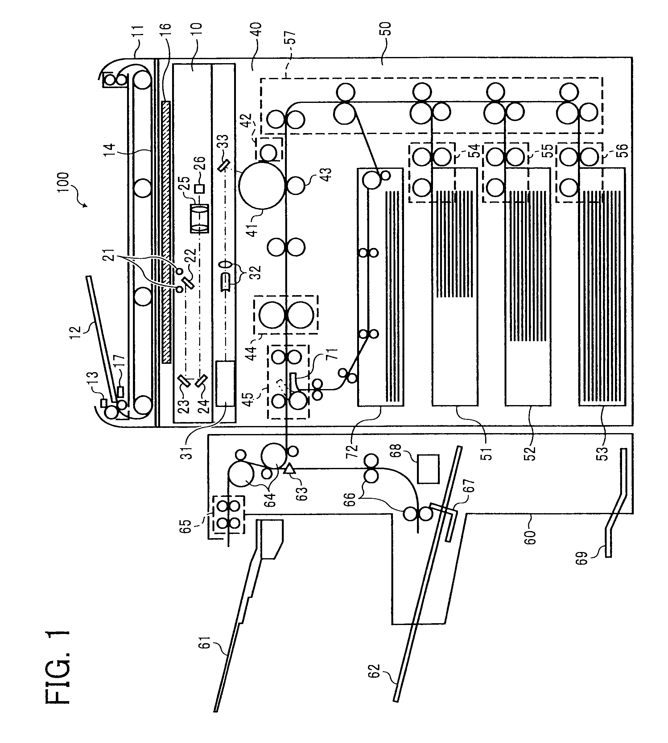
[0018]FIG. 1 is a schematic side view of an internal configuration of an MFP 100 according to an embodiment of the present invention. The MFP 100 includes a scanner engine 10, a plotter engine 40, a paper feed unit 50, and a paper discharging unit 60.

[0019]The scanner engine 10 scans an image from an original that is placed in a predetermined manner. The scanner engine 10 includes an automatic document feeder (ADF) 11, a document tray 12, a feeding roller 13, a feeding belt 14, an exposure glass 16, and a sensor 17 that detects whether the original is set. The scanner engine 10 includes an optical scanning...


PUM


Abstract

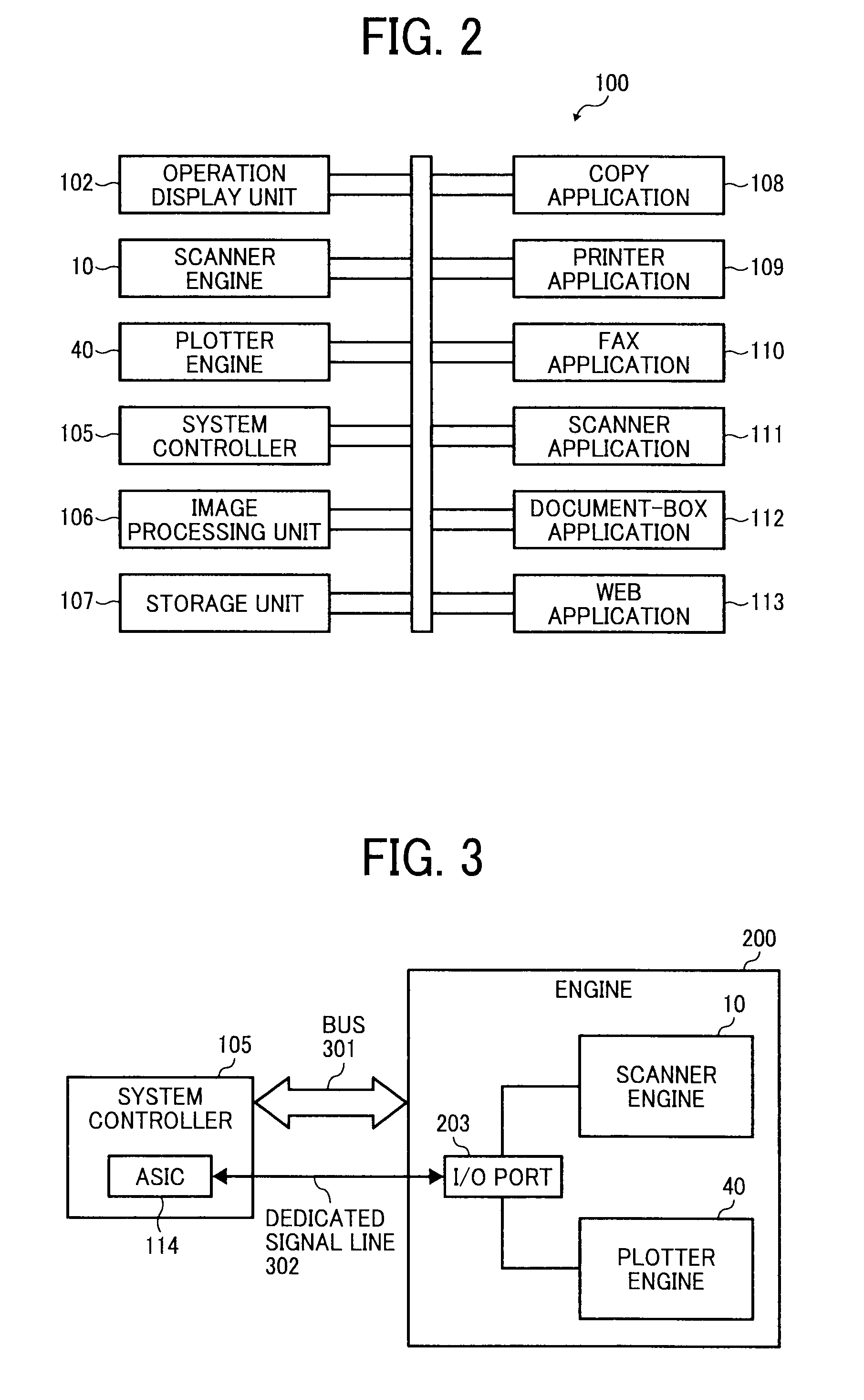
In an MFP, a system controller is connected to an engine via a universal transmission line and a dedicated transmission line. When MFP is powered, the system controller sends a mode signal to the engine via the dedicated signal line. If the mode signal indicates that the power mode is to be set to a normal mode, the engine activates predetermined components. The system controller and the engine then establish communication via the universal bus. After establishing the communication, if the mode signal indicates that the power mode is to be set to a mode other than the normal mode, the system controller sends a setting command to the engine via the bus to set the power mode to any of a plurality of power-saving modes.

Description

CROSS-REFERENCE TO RELATED APPLICATIONS[0001]The present application claims priority to and incorporates by reference the entire contents of Japanese Patent Application No. 2008-238678 filed in Japan on Sep. 17, 2008.BACKGROUND OF THE INVENTION[0002]1. Field of the Invention[0003]The present invention relates to an image forming apparatus that has a normal mode in which power is supplied to every component in the image forming apparatus and a power-saving mode in which power is supplied to only some of the components in the image forming apparatus.[0004]2. Description of the Related Art[0005]Devices with low-power consumption are in demand; therefore, research has been conducted in the field of image forming apparatuses, such as facsimile machines, printers, and copiers, into saving power when the apparatuses are on standby, for example, standby for receiving, standby for copying, and standby for printing.[0006]Various solutions offering power savings are widely used in image formin...

Claims


Application Information

Patent Timeline
IPC IPC(8): G06F3/12
CPCG03G15/80G03G15/5004
Inventor SASAKI, JUN
Owner RICOH KK
Learn More