Reflector system of fast reactor
- Summary
- Abstract
- Description
- Claims
- Application Information
AI Technical Summary
Benefits of technology
Problems solved by technology
Method used
Image

Examples
first embodiment
[0034]In this case, FIGS. 1 to 9 are views showing a reflector system of a fast reactor in a first embodiment according to the present invention.
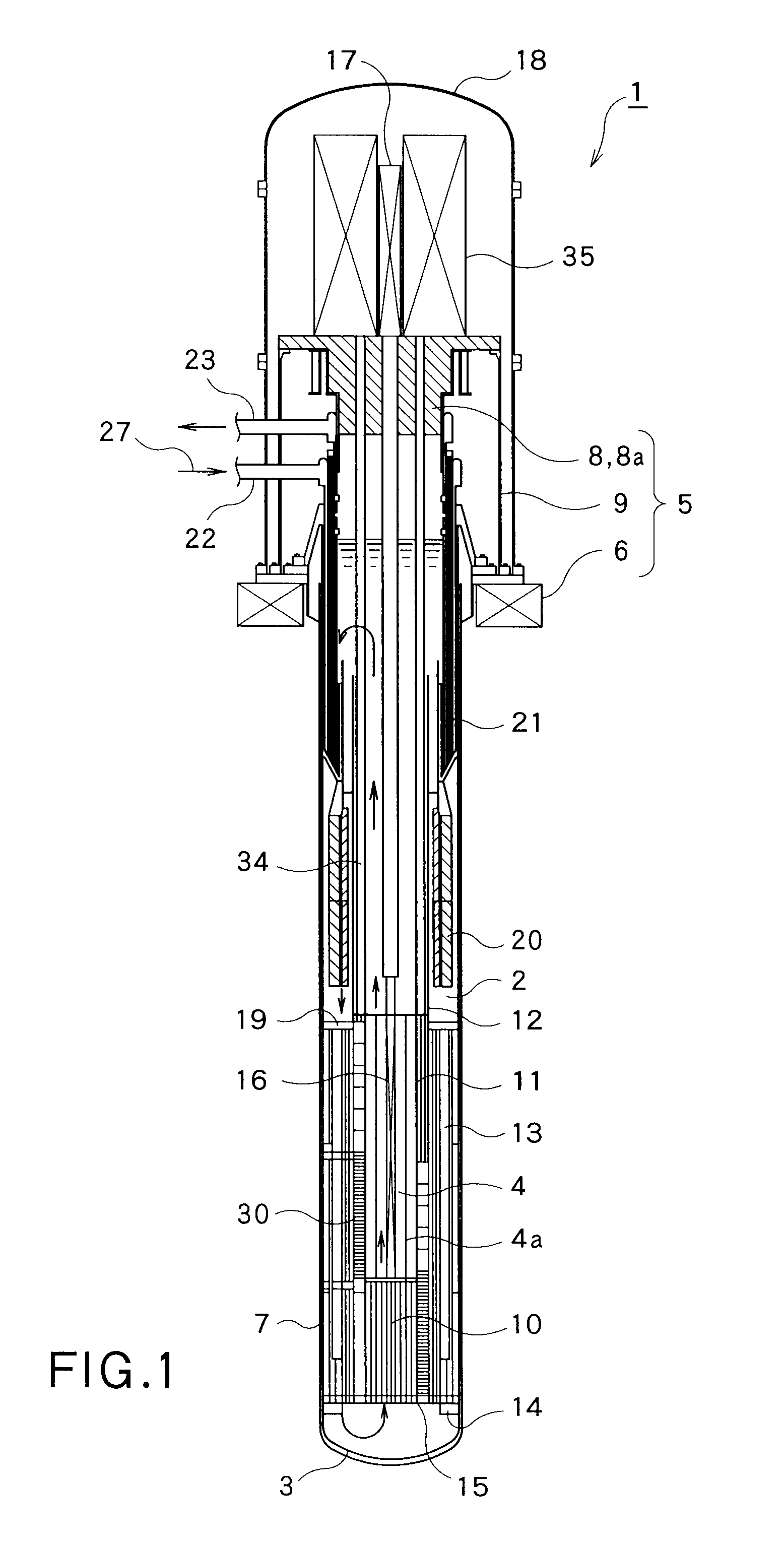
[0035]First of all, a description will be given of a whole structure of the fast reactor with reference to FIG. 1. As shown in FIG. 1, a fast reactor 1 comprises a reactor vessel 3 which is filled with a primary coolant 2 made of a liquid sodium as well as being held to a structure body 5 (in particular, a pedestal 6 mentioned below) of the fast reactor, and is formed as a closed-end cylindrical shape, and a reactor core 4 which is stored within the reactor vessel 3 and is immersed in the primary coolant 2. Among them, the reactor core 4 has a fuel assembly 4a constructed by a plurality of atomic fuels loaded in an inner portion thereof, and is formed as a cylindrical shape as a whole.
[0036]In this case, the fast reactor 1 is a reactor which can be driven continuously for ten and several years to some tens years, for example, about thirty y...
second embodiment
[0079]Next, a description will be given of a reflector system of a fast reactor in a second embodiment according to the present invention with reference to FIG. 10.
[0080]In the second embodiment shown in FIG. 10, the reflector system of the fast reactor is mainly different in a point that the load of the reflector is sensed by using a strain gauge, and the other structures are approximately the same as the first embodiment shown in FIGS. 1 to 9. In this case, in FIG. 10, the same reference numerals are attached to the same portions as those of the first embodiment shown in FIGS. 1 to 9, and a detailed description will be omitted.
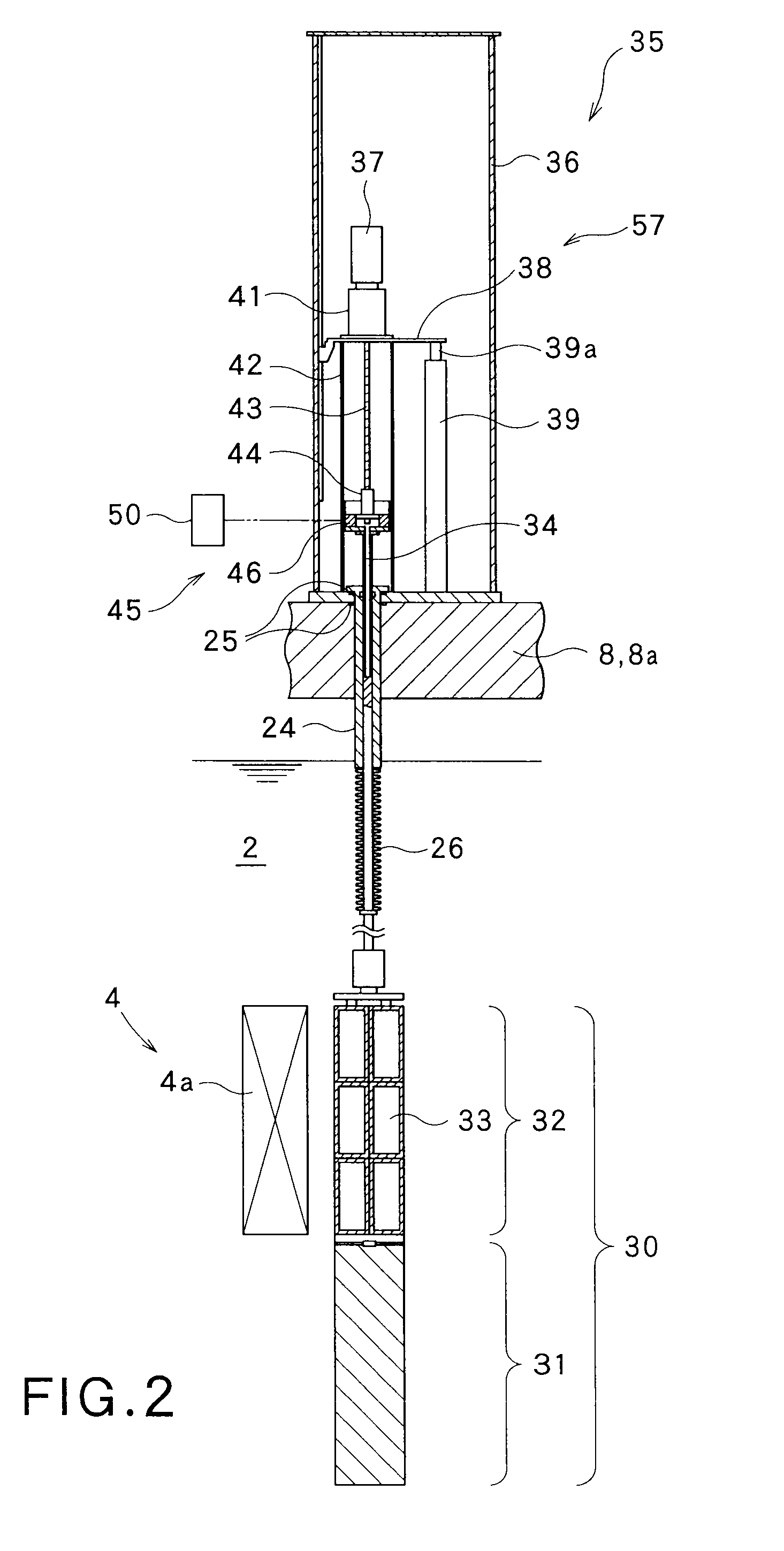
[0081]As shown in FIG. 10, a ball nut 44 (a coupling member) is coupled between an electric motor 37 and a drive shaft 34, that is, between a ball screw 43 and the drive shaft 34, and a first strain gauge 54 sensing a strain of the ball nut 44 is attached to the ball nut 44.
[0082]A second strain gauge 55 sensing a strain of an output shaft 39a is attached to...
third embodiment
[0087]Next, a description will be given of a reflector system of a fast reactor in a third embodiment according to the present invention with reference to FIGS. 11 and 12.
[0088]In the third embodiment shown in FIGS. 11 and 12, the reflector system of the fast reactor is mainly different in a point that the load of the reflector is sensed by using a torque sensing portion, and the other structures are approximately the same as the first embodiment shown in FIGS. 1 to 9. In this case, in FIGS. 11 and 12, the same reference numerals are attached to the same portions as those of the first embodiment shown in FIGS. 1 to 9, and a detailed description will be omitted.
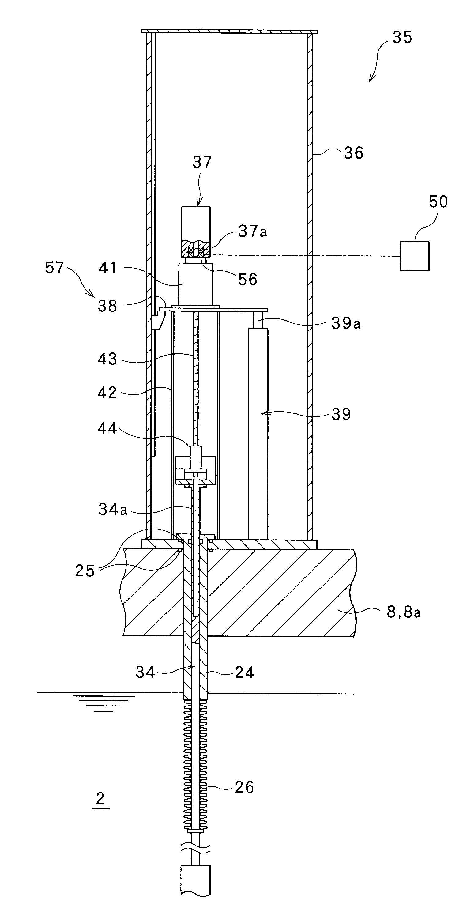
[0089]As shown in FIGS. 11 and 12, a strain torque measuring device (a torque sensing portion) 56 sensing a torque of a coupling shaft 40 coupled to a reduction gear 41 is provided between an electric motor 37 and a drive shaft 34, that is, a bearing portion 37a of the electric motor 34 and an electric motor side receiving tab...
PUM
 Abstract
Description
Claims
Application Information
 - R&D Engineer
- R&D Manager
- IP Professional
- Industry Leading Data Capabilities
- Powerful AI technology
- Patent DNA Extraction
Browse by: Latest US Patents, China's latest patents, Technical Efficacy Thesaurus, Application Domain, Technology Topic.
© 2024 PatSnap. All rights reserved.Legal|Privacy policy|Modern Slavery Act Transparency Statement|Sitemap