Encryption device

a technology of encryption device and encryption timing, which is applied in the direction of instruments, liquid/fluent solid measurement, generating/distributing signals, etc., can solve the problem of difficult estimation of the generation timing of suspend, and achieve the effect of enhancing the function

Inactive Publication Date: 2010-03-18
SHARP KK
View PDF6 Cites 19 Cited by
  • Summary
  • Abstract
  • Description
  • Claims
  • Application Information

AI Technical Summary

Benefits of technology

[0014]The present invention is made in view of the above problems and it is an object of the present invention to provide an encryption device with enhanced function to prevent an encryption key from being decrypted by consumption current analysis, by complicating alignment of consumption current waveforms.

Problems solved by technology

Especially, when the encryption processor clock signal is generated based on the pseudo-random number, since the timing of the encryption process varies at random, even when the same encryption target data is encrypted, its operation process time is not the same, whereby it is difficult to estimate the generation timing of the suspend even when the variation of the consumption current amount is externally detected and the consumption current waveforms are aligned.

Method used


Image

  • Encryption device
  • Encryption device
  • Encryption device

Examples


first embodiment

[0051]A first embodiment (referred to as “the present embodiment” occasionally hereinafter) of the device of the present invention will be described with reference to FIGS. 1 and 2.

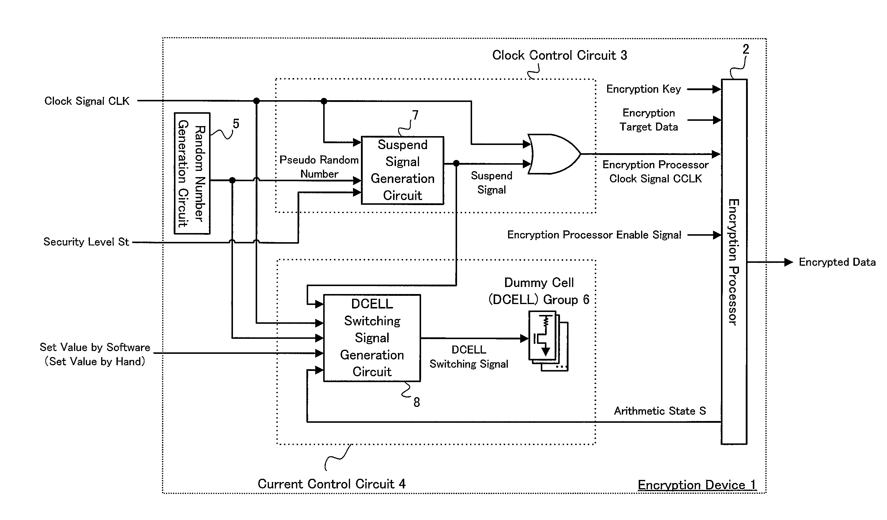
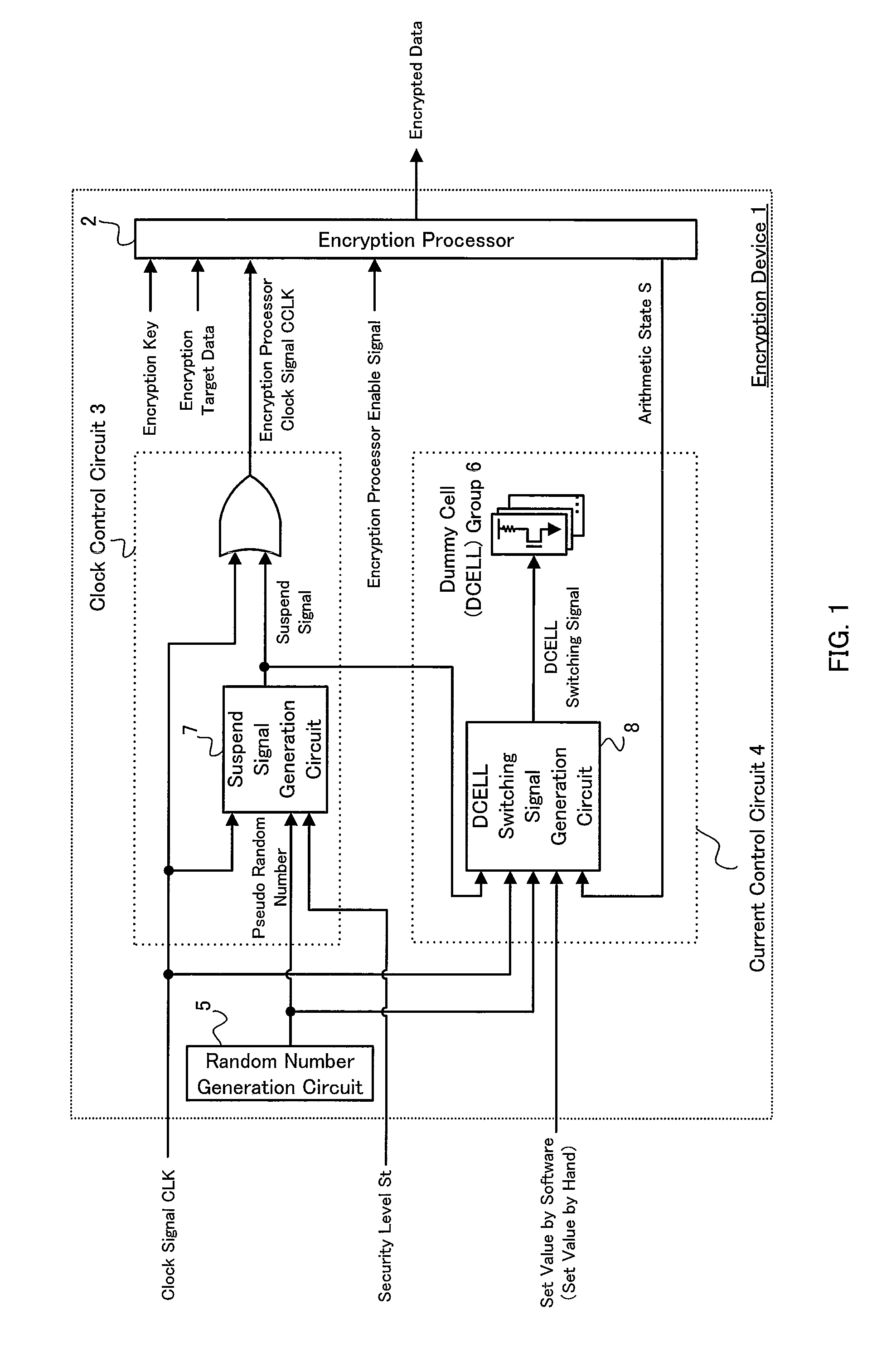
[0052]FIG. 1 is a block diagram showing a schematic configuration in the present embodiment of the device of the present invention. As shown in FIG. 1, an encryption device 1 according to the present invention includes an encryption processor 2, a clock control circuit 3, a current control circuit 4, and a random number generation circuit 5.

[0053]The encryption processor 2 receives encryption target data to be encrypted, an encryption key to be used in encrypting the data, an encryption processor clock signal CCLK serving as a timing signal for the encryption, and an encryption processor enable signal for switching between an operation state and a non-operation state. The encryption processor 2 generates encrypted data by encrypting the encryption target data based on the encryption key, in synchronizatio...

second embodiment

[0073]A description will be made of a second embodiment (referred to as “the present embodiment” occasionally hereinafter) of the device of the present invention with reference to FIG. 3. In addition, since the present embodiment is the same as the first embodiment except for a method for generating the clock signal CLK, a description will be made of a different part and the same components as the first embodiment will not be described.

[0074]FIG. 3 is a block diagram showing a schematic configuration of a clock selection circuit 9 to generate a clock signal CLK in the present embodiment.

[0075]The clock selection circuit 9 externally receives a system clock signal SCLK serving as a reference signal, a random number generation circuit 5a (that may be the same random number generation circuit as the random number generation circuit 5 in the first embodiment), and an encryption processor enable signal, and includes a clock selection signal generation circuit 10, a selector circuit 11, a...


PUM


Abstract

Provided is an encryption device with enhanced function to prevent an encryption key from being decrypted by consumption current analysis, by complicating alignment of consumption current waveforms. The encryption device comprises a clock control circuit adapted to receive a clock signal and a pseudo-random number, and perform a suspend process and a resume process to the clock signal based on the pseudo-random number to generate an encryption processor clock signal; an encryption processor adapted to perform an encryption process to encryption target data in synchronization with the encryption processor clock signal; and a current control circuit adapted to obtain an arithmetic state showing an operational state of the encryption processor to adjust a consumption current amount based on the arithmetic state.

Description

CROSS-REFERENCE TO RELATED APPLICATIONS[0001]This application is a National Phase filing under 35 U.S.C. § 371 of International Application No. PCT / JP2007 / 065810 filed on Aug. 13, 2007, and which claims priority to Japanese Patent Application No. 2006-293873 filed on Oct. 30, 2006.TECHNICAL FIELD[0002]The present invention relates to an encryption device with enhanced function to prevent an encryption key from being decrypted by consumption current analysis.BACKGROUND ART[0003]Since information networking has been advanced nowadays, information has a great value and accordingly, the security for the information is getting important. According to the security, “encryption technique” that aims to hide the information is positioned as one of the core techniques among various security techniques.[0004]The encryption designates specific symbol and character or its procedure and system arranged so that the contents thereof cannot be understood by outsiders but understood by parties concer...

Claims


Application Information

Patent Timeline
Patent Type & Authority Applications(United States)
IPC IPC(8): H04L9/28G06F1/04G06F1/26
CPCH04L9/003H04L2209/12H04L2209/08
Inventor OKITA, YOSHITAKA
Owner SHARP KK
Why Eureka
Try Eureka