Burner the Direction and/or Size of the Flame of Which Can Be Varied, and Method of Implementing It

a burner and flame direction technology, applied in the direction of lighting and heating apparatus, combustion types, combustion using lump and pulverizing fuel, etc., can solve the problems of limiting the number of operating modes, and limiting the complexity and cost of manufacturing the burner. , to achieve the effect of wide variation in the direction and/or aperture of the flame, and limiting the complexity and cost of manufacturing

Inactive Publication Date: 2010-03-18
LAIR LIQUIDE SA POUR LETUDE & LEXPLOITATION DES PROCEDES GEORGES CLAUDE +1
View PDF22 Cites 28 Cited by
  • Summary
  • Abstract
  • Description
  • Claims
  • Application Information

AI Technical Summary

Benefits of technology

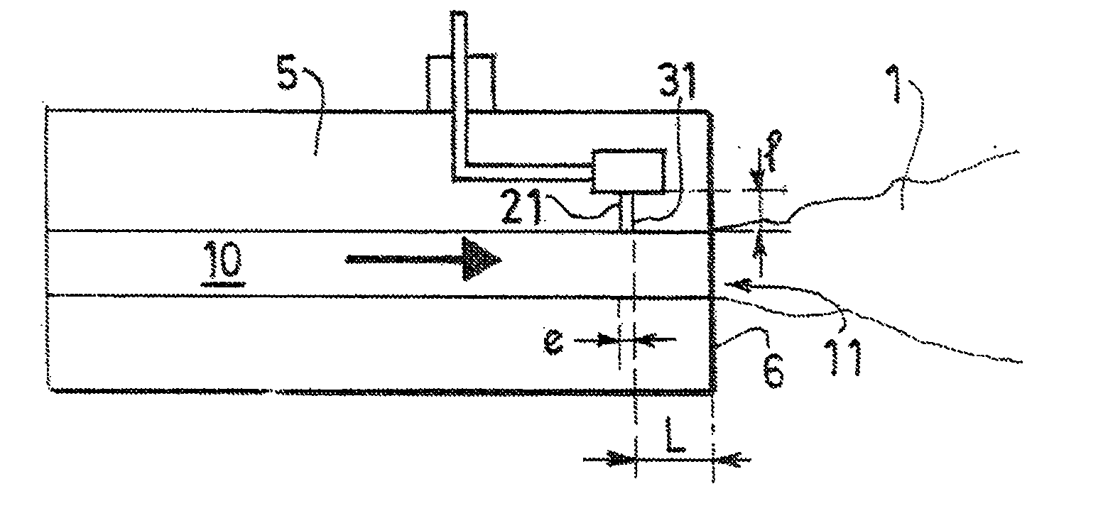
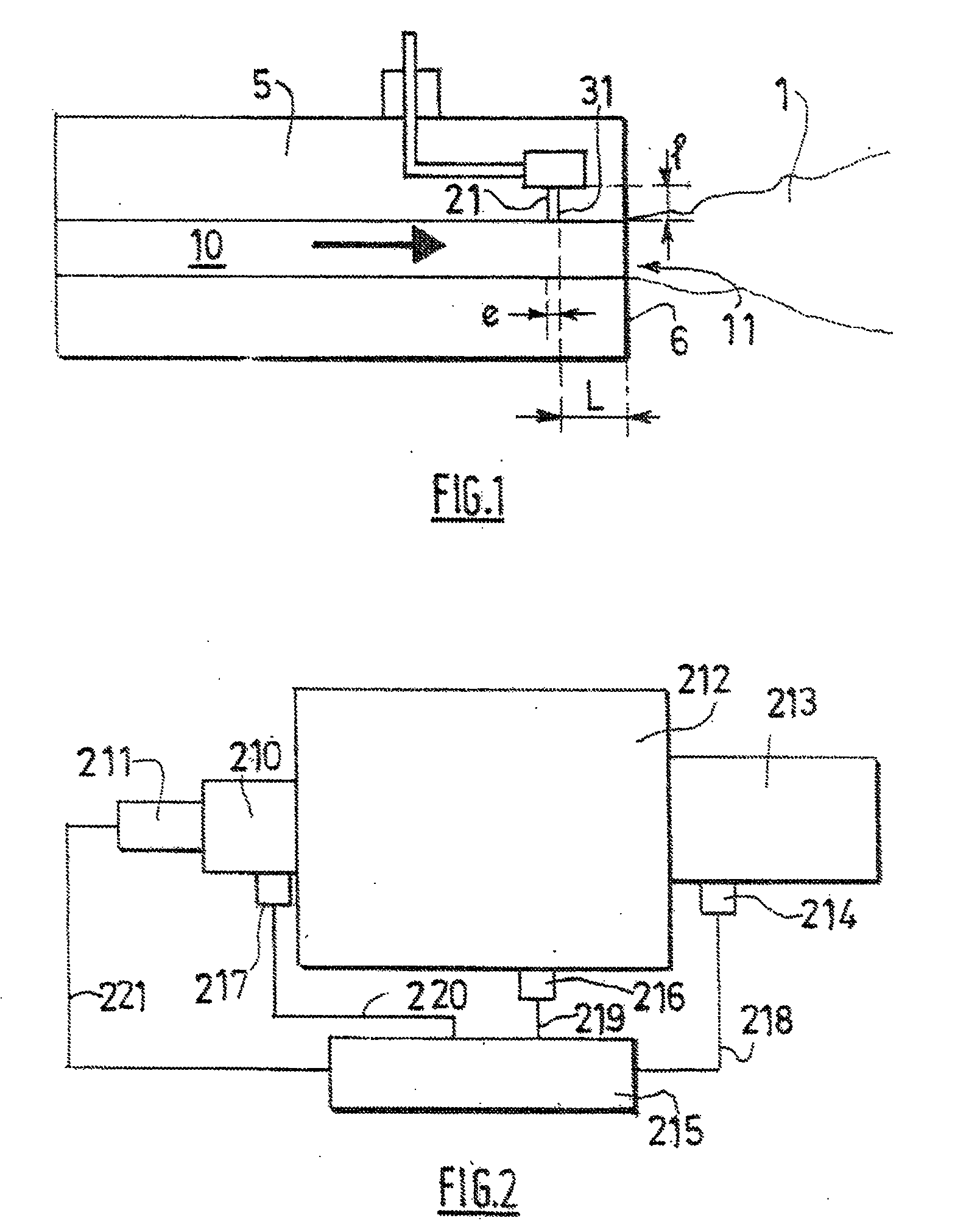
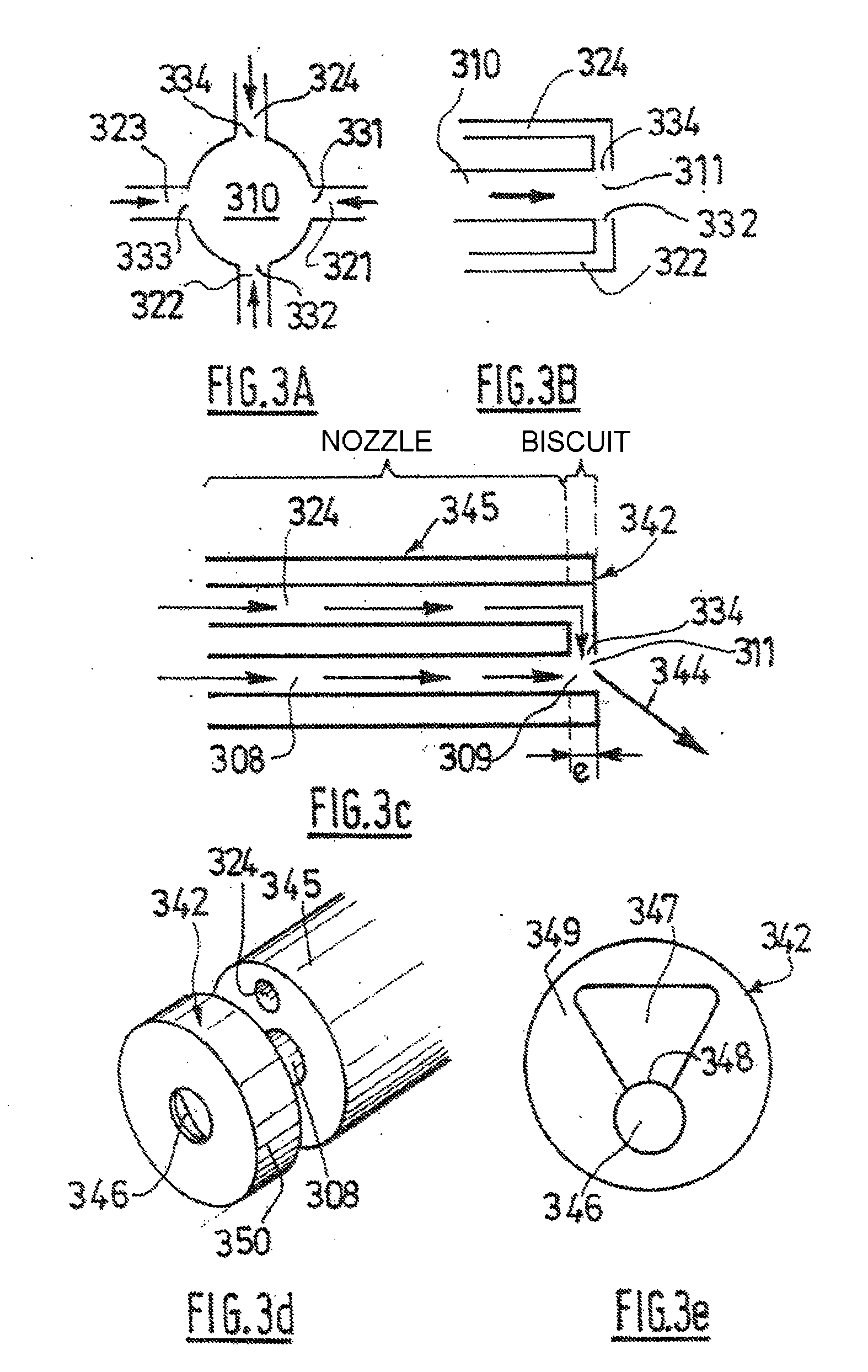
[0017]As explained in detail hereinbelow, the invention thus makes it possible to vary the direction and / or the aperture of the flame obtained from the burner by modifying the impulse of at least one secondary jet with said means.
[0018]Preferably, the means for controlling the impulse of the at least one secondary jet are means making it possible to control the ratio between the impulse of the secondary jet and the impulse of the primary jet. The invention thus makes it possible to produce a wide variation in direction and / or aperture of a flame without using mechanical means, potential sources of malfunction, in particular in hostile environments, such as fire boxes with high temperature and / or polluted or corrosive atmosphere.
[0019]The control means make it possible in particular to actively or dynamically control the impulse of the at least one secondary jet, that is, they make it possible to vary the pulse or pulses without interrupting the operation of the burner / without interrupting the flame. The appliance according to the invention thus allows for an equally dynamic variation of the direction and / or the aperture of the flame.
[0020]Preferably, the number of secondary jets interacting with the primary jet to obtain the desired effect on the flame will be minimized so as to limit the complexity and the cost of manufacturing the burner but also the complexity and the cost of the system for feeding and regulating the flow rates of the fluids if the secondary jets are driven independently. For example, a single-direction effect can be obtained with a single secondary jet.

Problems solved by technology

Certain combustion technologies allow discrete and very limited numbers of operating modes.
However, the modifications of the point and / or of the operating mode are more often than not inadequate for optimizing the performance characteristics of the burners or of the methods that use these burners in all conditions.
This trade-off is reflected in a melting time below which any gain in productivity will be counterbalanced by a degradation of the quality of the product or by a reduction in the lifetime of the oven.
However, the maximum deflection of the flame is in practice limited to approximately 15° from the median position to the extreme position (30° at most, in all), not allowing the incident flame to sweep a wide surface of a charge, and the construction of the corresponding burner is relatively heavy because there is a need for a plurality of orifices for the primary jets of oxidant and a plurality of orifices for the secondary jets of oxidant.

Method used


Image

  • Burner the Direction and/or Size of the Flame of Which Can Be Varied, and Method of Implementing It
  • Burner the Direction and/or Size of the Flame of Which Can Be Varied, and Method of Implementing It
  • Burner the Direction and/or Size of the Flame of Which Can Be Varied, and Method of Implementing It

Examples


example 1

Case of Solid Material in the Oven

[0137]Burners according to the invention are used for the incidence of the flame to be variable. (The term “incidence” should be understood to mean the angle of the flame relative to the horizontal). When the incidence is zero, the flame is horizontal. When the incidence is non-zero, the flame is inclined under the horizontal and directed toward the hearth of the smelting basin of the oven.

[0138]The burners inject each jet of fluid into the chamber of the oven, but this type of injector can be used only for fluid (oxidant or fuel) of higher impulse when the latter can interact with that of lesser impulse so as to obtain the desired deflection of the flame, typically, the oxidant in the case of an air / gaseous fuel burner, or oxygen / gaseous fuel burner.

[0139]In the first part of the aluminum smelting cycle, when the metal is mostly present in the solid state, the direction of the flame is adjusted for the latter to have a non-zero incidence (axis of t...

example 2

Creating a Uniform Transfer of Energy to the Charge

[0147]Burners according to the invention are used for the orientation of the flame in a horizontal plane to be able to be modified on demand according to the control ratio of each burner as illustrated in FIG. 13.

[0148]Each fluid jet is injected into the chamber of the oven through a burner according to the invention, but for jets situated in one and the same horizontal plane or in horizontal planes that are very close together (no more than one to two jet diameters apart), it is possible to use these injectors only for the peripheral jets when the latter can interact with the other jets to be deflected.

[0149]The variation of the horizontal orientation can be achieved in both left and right directions either by equipping each main jet with two lateral actuating jets, or by equipping each peripheral main jet with a single actuating jet, capable of actuating the main jet in the horizontal direction but in directions opposite to each o...

example 3

Flame with Variable Incidence on Charge and Laterally Sweeping the Charge


PUM


Abstract

Burner comprising at least one passage for injecting at least a primary jet, such as a jet of oxidant and/or fuel and/or of a premix of oxidant and fuel, and means of injecting at least one secondary jet of fluid opening into said passage, the interaction between the primary jet and the at least one secondary jet making it possible to vary the direction and/or the size of the flame. Use of said burner for heating a charge with the variable-direction and/or variable-size flame.

Description

[0001]The present invention relates to a burner that makes it possible to vary the direction and / or the aperture of the flame, said burner comprising at least one channel for injecting at least one main or primary jet and at least one channel for injecting an actuating or secondary jet. The primary jet is typically a jet of oxidant and / or of fuel and / or of an oxidant-fuel premix.[0002]It also relates to the use of said burner to vary the direction and / or the aperture of a flame. It also relates to a method of heating a charge using this burner in which the direction and / or the aperture of the flame is varied.CONTEXT OF THE INVENTION[0003]Most ovens or industrial boilers use burners that operate in non-premixed combustion mode, that is, a mode in which the oxidant and the fuel arrive separately as far as the place of combustion. The fuel and the oxidant are then mixed, in part (locking of the flame in a refractory port or prechamber block) or in total, inside the combustion chamber. ...

Claims


Application Information

Patent Timeline
Patent Type & Authority Applications(United States)
IPC IPC(8): F23D11/36F23D99/00
CPCF23D14/84
Inventor ZAMUNER, BERNARDDOCQUIER, NICOLASLABEGORRE, BERNARDLEDERLIN, THOMASPOINSOT, THIERRYFAIVRE, VINCENT
Owner LAIR LIQUIDE SA POUR LETUDE & LEXPLOITATION DES PROCEDES GEORGES CLAUDE
Why Eureka
Try Eureka