Steering system

Inactive Publication Date: 2010-03-18
HONDA MOTOR CO LTD
View PDF39 Cites 16 Cited by
  • Summary
  • Abstract
  • Description
  • Claims
  • Application Information

AI Technical Summary

Benefits of technology

[0061]According to the fourth aspect of the present invention, when the absolute value of the steering angular velocity of the steering wheel is changed in the vicinity of zero by the second correction unit corresponding to the steering state (for example, “addi

Problems solved by technology

If the driver tries to turn the steering wheel quickly when the ratio is quickened in the low vehicle speed range, the steering wheel of the steering system provided with such variable transfer ratio mechanism and electric power steering unit may become difficult to turn because deficiency of auxiliary power occurs due to an influence of counter electromotive voltage of an EPS (Electric Power Steering) motor, i.e., a power source of the electric power steering unit, even though the electric power steering unit tries to generate the auxiliary power so as to be able to turn the turning wheel largely and quickly.
Still more, w

Method used


Image

  • Steering system
  • Steering system
  • Steering system

Examples


first embodiment

[0087]Next, with reference to FIGS. 1-5, a steering system of a first embodiment according to the present invention will be explained.

(Steering System)

[0088]First, with reference to FIGS. 1-3, the whole structure of the steering system will be explained.

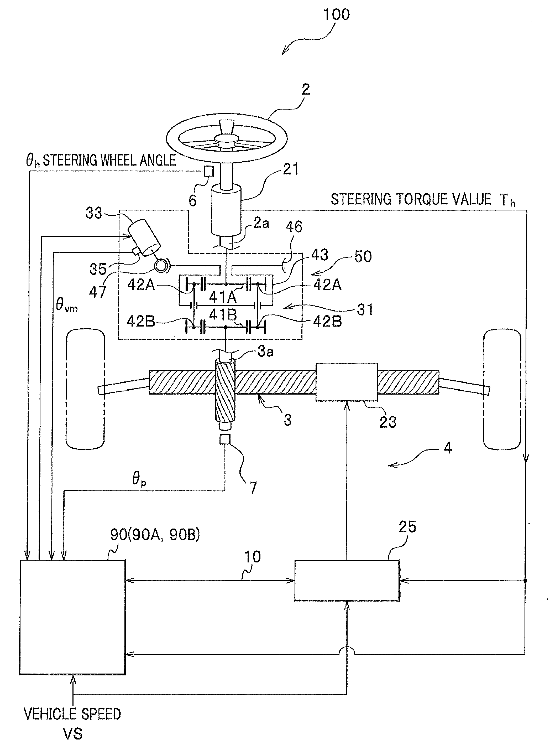
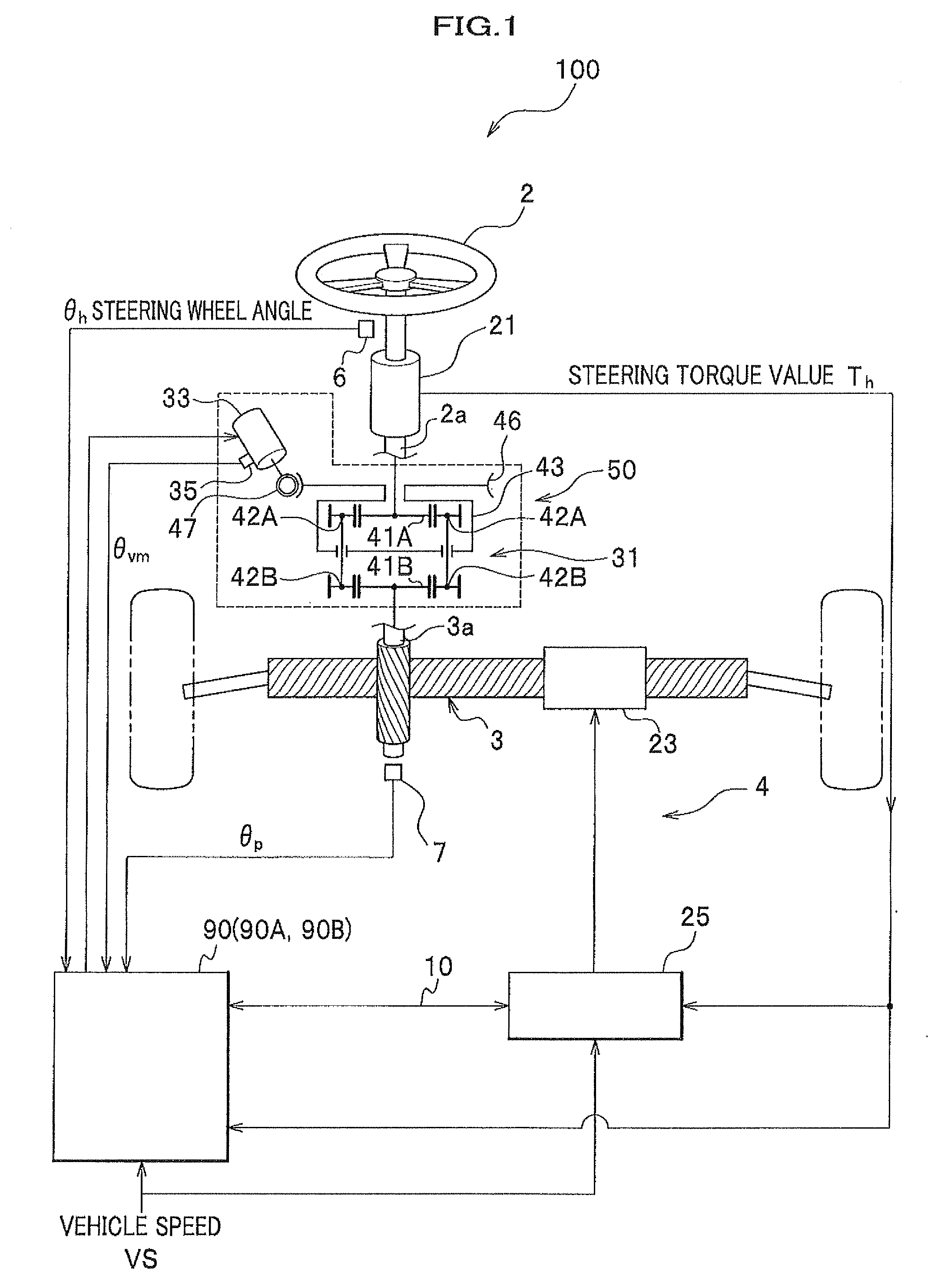
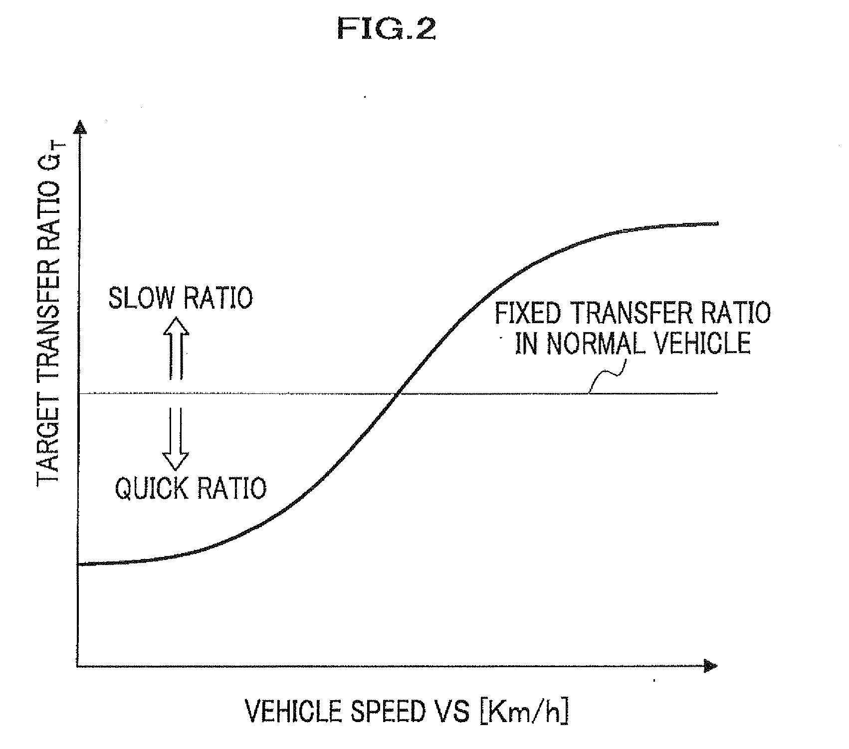
[0089]FIG. 1 is a structural block diagram of the steering system of the first embodiment. FIG. 2 is a graph indicating a value of a target transfer ratio set corresponding to vehicle speed, and FIG. 3 is a functional structural block diagram of the variable transfer ratio mechanism controlling ECU.

[0090]As shown in FIG. 1, the steering system 100 is provided with a steering wheel 2, a rack & pinion mechanism 3, an electric power steering unit (electric power steering) 4, and a variable transfer ratio mechanism 50.

[0091]The electric power steering unit 4 has a torque sensor 21 for detecting a steering torque applied to a rotary shaft 2a of the steering wheel 2, an EPS motor 23 for driving a rack to change the turning angle of the tur...

modified first embodiment

[0166]Next, with reference to FIG. 5B, a modified first embodiment will be explained.

[0167]In the first embodiment, the data 38a of the correction factor K2 used in the correction factor setting section 38A (see FIG. 3) is the continuous function A or the continuous function B shown in. FIG. 5A. However, the function is not limited to the above. A discontinuous function C whose variable is the absolute value of the steering wheel angular velocity |ωh| shown in FIG. 5B may be used. In the example of the discontinuous function C, it represents characteristics that the correction factor K2=0.0 when the absolute value of the steering wheel angular velocity |ωh| is a value from zero to the predetermined threshold value ε0 which is less than the threshold value ε1, and the correction factor K2 jumps to +1.0 and is kept at +1.0 when the absolute value of the steering wheel angular velocity |ωh| exceeds the threshold value ε0.

[0168]According to this embodiment, when the driver quickly steer...

second embodiment

[0170]Next, with reference to FIGS. 1 and 8-11, a steering system of a second embodiment according to the present invention will be explained.

[0171]FIG. 8 is a functional structural block diagram of a steering system in a variable transfer ratio mechanism controlling ECU of this embodiment, FIG. 9 is a detailed functional structural block diagram of a correction factor setting section 38B which is a second correction unit, and FIGS. 10A and 10B show example values of the correction factors K2 which are second correction factors set corresponding to the absolute value of the steering wheel angular velocity. FIG. 11 is a flowchart showing a flow of correction control by a correction factor setting section 20A and a correction factor setting section 38B in the second embodiment.

[0172]The variable transfer ratio mechanism controlling ECU 90B of the second embodiment (see FIG. 8) differs from the variable transfer ratio mechanism controlling ECU 90A of the first embodiment (see FIG. 3) i...


PUM


Abstract

An object of the present invention is to provide a steering system which does not cause the driver to feel the steering reactive force shock when the operation of the steering wheel is stopped, and which enables the driver to operate the steering wheel comfortably. In order to achieve the above object, there is provided a steering system in which a transfer ratio of a steering angle of a steering wheel to a turning angle of a turning wheel is changed by a variable transfer ratio mechanism, and an auxiliary power is generated during steering by an electric power steering, including: a transfer ratio variable motor for changing the transfer ratio, in which a steering angular velocity of the steering wheel is calculated, and when an absolute value of the steering angular velocity becomes equal to or less than a predetermined value, a current value flowing through the transfer ratio variable motor is set to zero.

Description

CROSS REFERENCE TO RELATED APPLICATIONS[0001]The present application claims benefit of the filing date of Japanese patent application No. 2008-224894 filed on Sep. 2, 2008, which is incorporated herein by reference.[0002]1. Field of the Invention[0003]The present invention relates to a steering system which changes a transfer ratio of a steering angle of a steering wheel to a turning angle of a turning wheel by a variable transfer ratio mechanism and generates auxiliary power during steering by an electric power steering unit.[0004]2. Description of the Related Art[0005]Heretofore, a steering system having a variable transfer ratio mechanism and an electric power steering unit has been proposed. The variable transfer ratio mechanism enables a driver to largely turn a turning wheel with less steering operation by setting a transfer ratio (=an angle of steering wheel / angle of turning wheel) to be small (by quickening the ratio) in a low vehicle speed range during parking and the like,...

Claims


Application Information

Patent Timeline
IPC IPC(8): G06F19/00B62D5/04B62D6/00B62D101/00B62D113/00B62D119/00B62D137/00
CPCB62D5/008B62D6/002B62D5/046
Inventor YAMAGUCHI, TAKUYAAKUTA, YOSHIMITSU
Owner HONDA MOTOR CO LTD
Why Eureka
Try Eureka