Microgravimeter for geophysical prospecting

a geophysical prospecting and microgravimeter technology, applied in the field of apparatus and a method for measuring gravitational acceleration, can solve the problems of not being able to adapt to be used on the ground, not being portable, and not having the effect of strict control, so as to reduce the cost of a measurement campaign remarkably, and reduce the time necessary

Inactive Publication Date: 2010-03-25
ENI SPA
View PDF3 Cites 15 Cited by
  • Summary
  • Abstract
  • Description
  • Claims
  • Application Information

AI Technical Summary

Benefits of technology

[0012]It is another feature of the present invention to provide such an apparatus for reducing the time necessary for each single measurement, in order to reduce remarkably the cost of a measurement campaign.
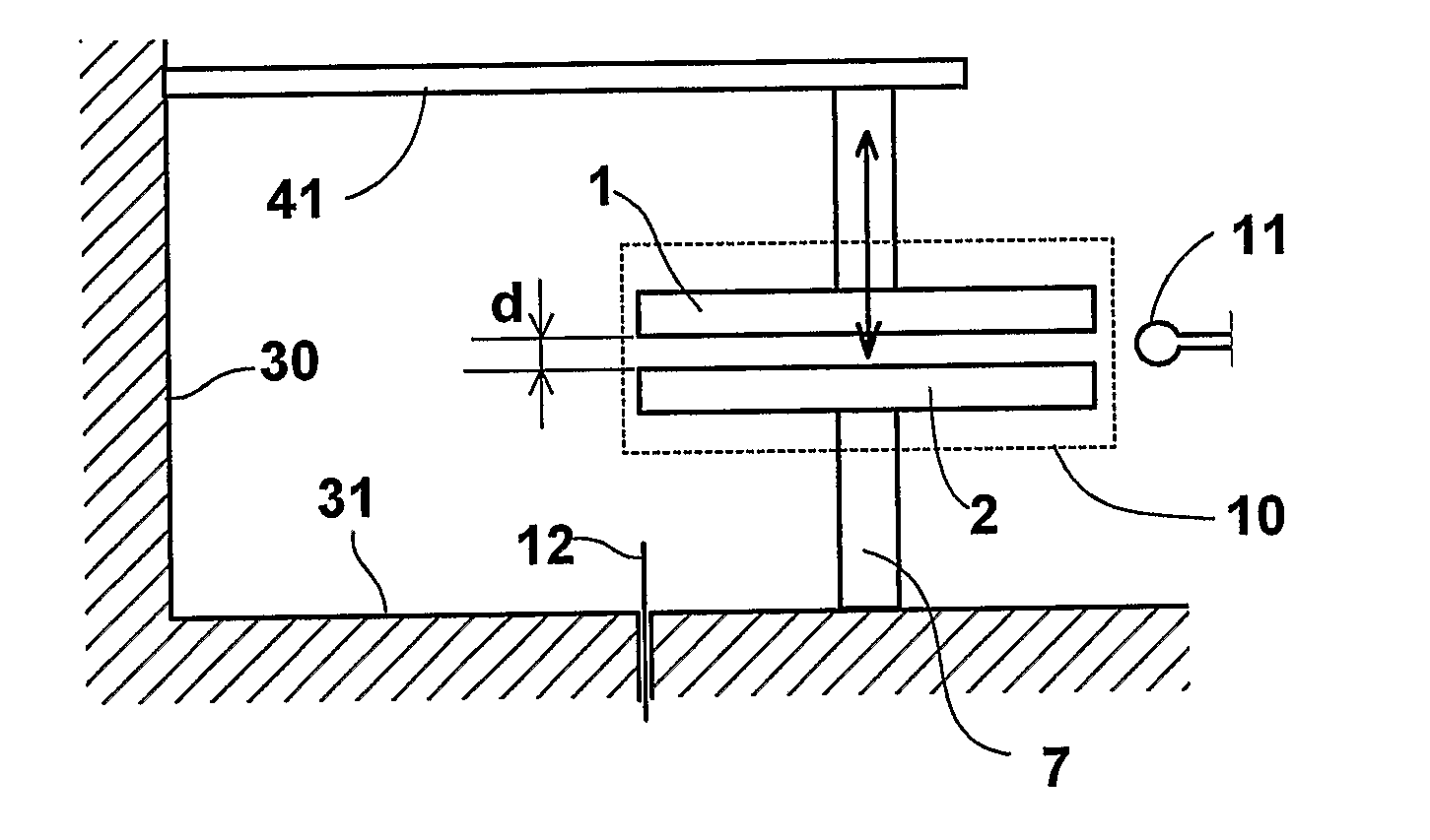
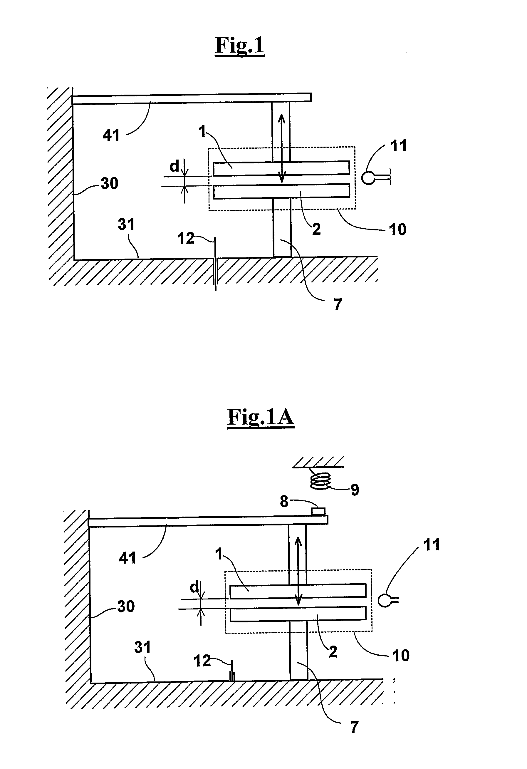
[0046]Preferably, means are provided for adjusting the unexcited distance between the discs, comprising a piezoelectric device on which said first mass is mounted. This way it is possible to control the electric resonance frequency f0 and the transduction factor ∂f / ∂l between the distance 1 and the frequency f0.

Problems solved by technology

This apparatus, however, have the drawback of having the need of a strict control of the hysteresis and of the mechanical drift, to avoid that such effects overcome the useful signals.
These instruments have very high resolution, for example and less than 0,01 Eötvös, but are not portable and not adapted to be used on the ground.
The very high performances of this instrument are however associated with a corresponding high cost, encumbrance and weight.
However, it is not easily manageable, for the size of the inertial platform and for the need of having a liquid helium refrigeration system.

Method used


Image

  • Microgravimeter for geophysical prospecting
  • Microgravimeter for geophysical prospecting
  • Microgravimeter for geophysical prospecting

Examples


example

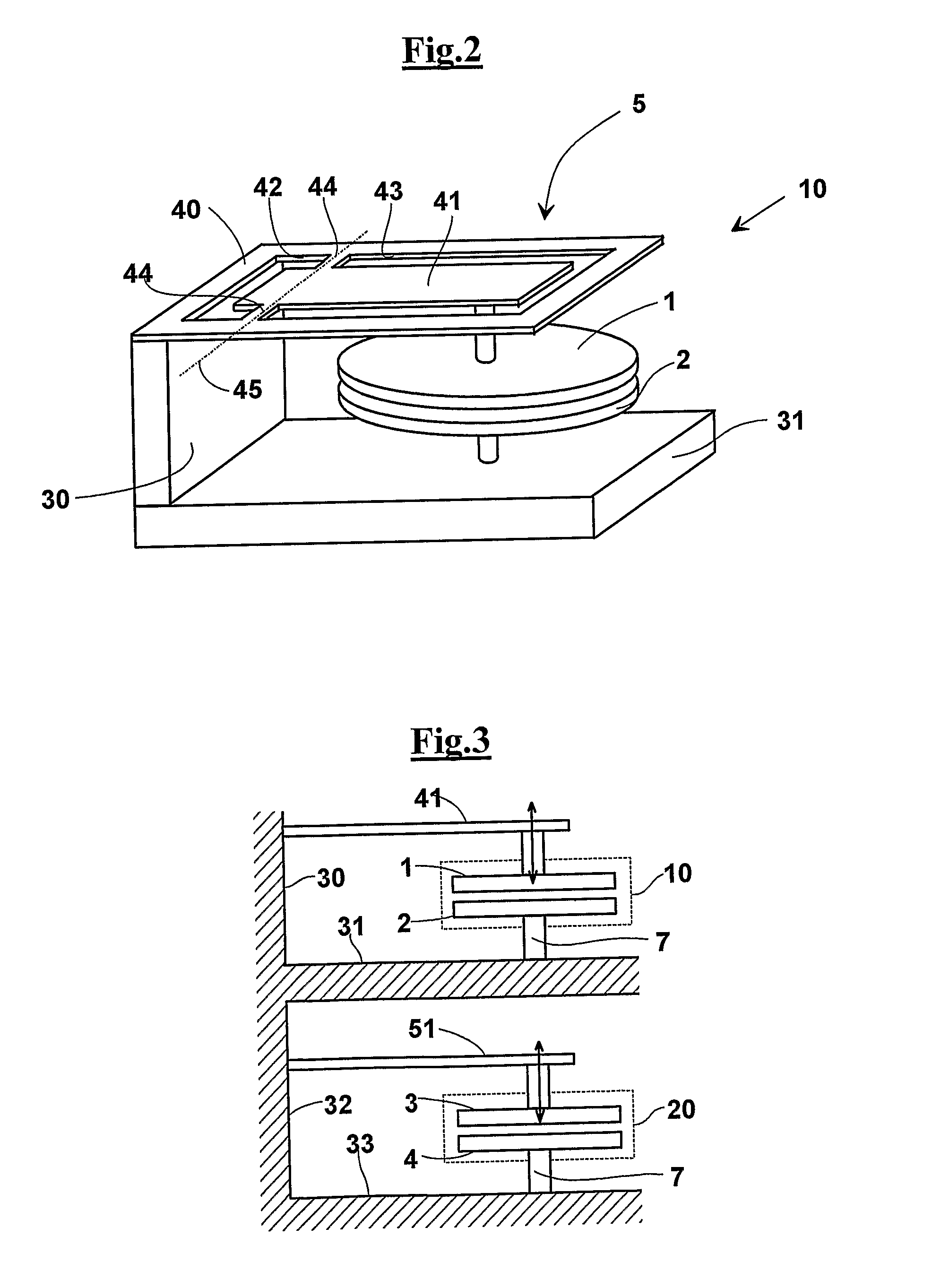
[0079]An example is given below of sizing a gravity gradiometer according to the invention. This example relates to a gradiometer having two microwave resonators WGM formed each by two sapphire discs substantially equal to each other (see FIG. 4), with diameter 42 mm, height 5 mm, εr=9.750 and εz=11.350, of which both the merit factors of the various resonances in the band of interest, about 10-12 GHz, both the values of the transfer coefficient df / dz have been determined to the light of the results obtained has been chosen the way TM11,1,0+d, which represents the higher factor Qx(df / dz), i.e. about 300000 MHz / mm, having a factor of merit Q≈58000 and df / dz≈5 MHz / mm, with a gap between the two discs of about 100 μm.

[0080]For achieving a sensitivity necessary to measure 10 Eötvös, very small displacements have to be measured, about 10−13 m, and among the many causes of noise the effect of the temperature on the apparatus as a whole should be ascertained, i.e. torsion pendulum+microwav...


PUM


Abstract

An apparatus and a method for measuring the gravitational acceleration on the ground, for example adapted to geophysical explorations applied to mining, comprising a base frame (31), a resonator (10) having a first disc of sapphire (2) integral to said base frame (31), an a second disc of sapphire (1) arranged at a minimum distance from said first mass (2) and aligned vertically with respect to said first mass (2) such that said first and said second disc (1 and 2) form a resonator for electromagnetic signals (10); a cantilever arm (41) connected to said base frame (31) and holding resiliently the second disc (1) in order to provide a steady elastic modulus; a magnetic probe (11) for applying an electromagnetic signal to said resonator (10) arranged according to a plane existing between the two discs (1 and 2); a linear electric probe (12), arranged under the fixed disc (2) aligned vertically with respect to its side edge, for measuring a resonance frequency of said resonator responsive to said electromagnetic signal, means for correlating the variation of said resonance frequency to a variation of distance between said discs (1 and 2), and means for correlating the variation of distance to local gravitational acceleration. The support (7) has variable length for adjusting the unexcited distance d between the discs (1 and 2). Preferably, a first (10) and a second resonator are provided as above defined coupled and mounted on two respective base frames integral to each other for measuring the gravitational acceleration gradient in a vertical direction. Furthermore, the resonators are contained in a closed box in which vacuum conditions are created.

Description

FIELD OF THE INVENTION[0001]The present invention relates to an apparatus and a method for measuring the gravitational acceleration on the ground.[0002]Among possible applications there are fieldworks for ore and oil explorations or for environmental purposes, for detection in the underground cavities or in any case of discontinuity structures of natural or artificial origin. Other applications comprise structural researches on a larger scale with an air or marine carrier.DESCRIPTION OF THE TECHNICAL PROBLEM[0003]The geophysical analysis by means of microgravimetric prospecting is a methodology with many potentialities and increasing development.[0004]Sensors for measuring the gravitational acceleration are known. A first type of sensors is commercialized by the company LRS (LaCoste & Romberg—Scintrex) Inc., and consists essentially of a spring, maintained in critic working conditions in order to enhance minimum variation of the force exerted on it. This apparatus measures values of...

Claims


Application Information

Patent Timeline
Patent Type & Authority Applications(United States)
IPC IPC(8): G01V7/00
CPCG01V7/005
Inventor BEVERINI, NICOLOFIDECARO, FRANCESCODE MICHELE, ANDREAMANGO, FRANCESCOBERTOLINI, ALESSANDRO
Owner ENI SPA
Why Eureka
Try Eureka