Method and apparatus for manufacturing fused silica crucible, and the fused silica crucible

a technology of fused silica crucible and manufacturing method, which is applied in the direction of manufacturing tools, crystal growth process, and protective fluid, etc., can solve the problems of difficult property control, excessive heat amount of the center portion enclosed by the electrode, and difficulty in uniform heating the inside of the crucible or the like, etc., to prevent excessive heating of the bottom of the crucible, good transparent glass layer, and stable arc

Active Publication Date: 2010-03-25
SUMCO CORP
View PDF6 Cites 26 Cited by
  • Summary
  • Abstract
  • Description
  • Claims
  • Application Information

AI Technical Summary

Benefits of technology

[0075]According to the invention, by defining the electrode position, a stable ring-shaped arc is formed along the inner peripheral surface of the mold to heat and melt the vitreous silica powder on the inner peripheral surface of the mold. In addition, an arc crossing the center portion of the ring is not substantially formed. Therefore, excessive heating of the bottom of the crucible is prevented, and the crucible can be uniformly heated from the wall to the bottom. Accordingly, a fused silica crucible having a good transparent glass layer can be manufactured. In addition, there are advantages in that the arc is stable, the heating range is wide, so that a fused silica crucible as a large crucible with good quality can be obtained.

Problems solved by technology

However, in the configuration of the six six-phase AC electrodes, as illustrated in FIG. 6 of JP-A-2003-335532, an arc discharge between opposed electrodes is more likely to occur than between neighboring electrodes, so that the discharge heat amount of a center portion enclosed by the electrodes increases excessively to a greater extent than the heat amount of peripheral portions, and there is difficulty in uniformly heating the inside of the crucible or the like.
In addition, the internal surface state of the crucible has a direct effect on properties of a pulled semiconductor single crystal, so that very difficult property control is required.

Method used


Image

  • Method and apparatus for manufacturing fused silica crucible, and the fused silica crucible
  • Method and apparatus for manufacturing fused silica crucible, and the fused silica crucible
  • Method and apparatus for manufacturing fused silica crucible, and the fused silica crucible

Examples


example 1

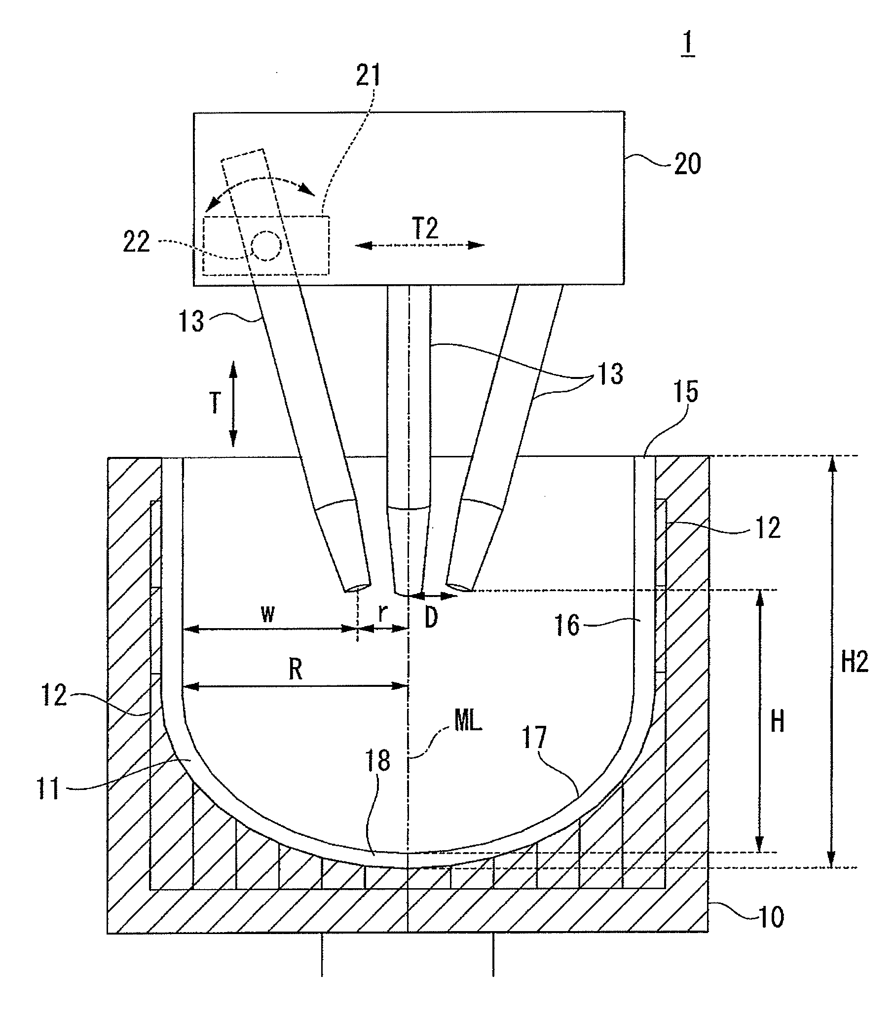
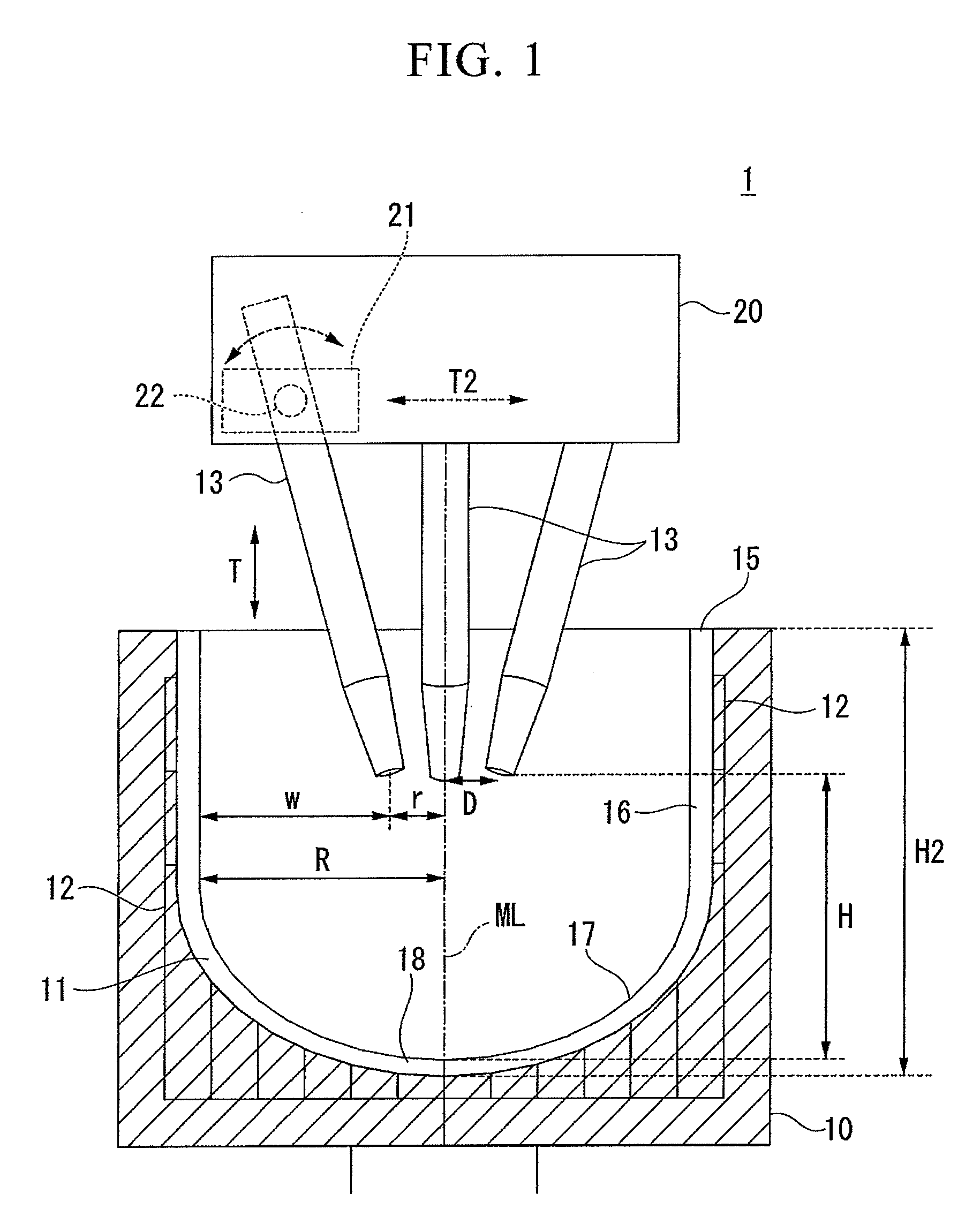
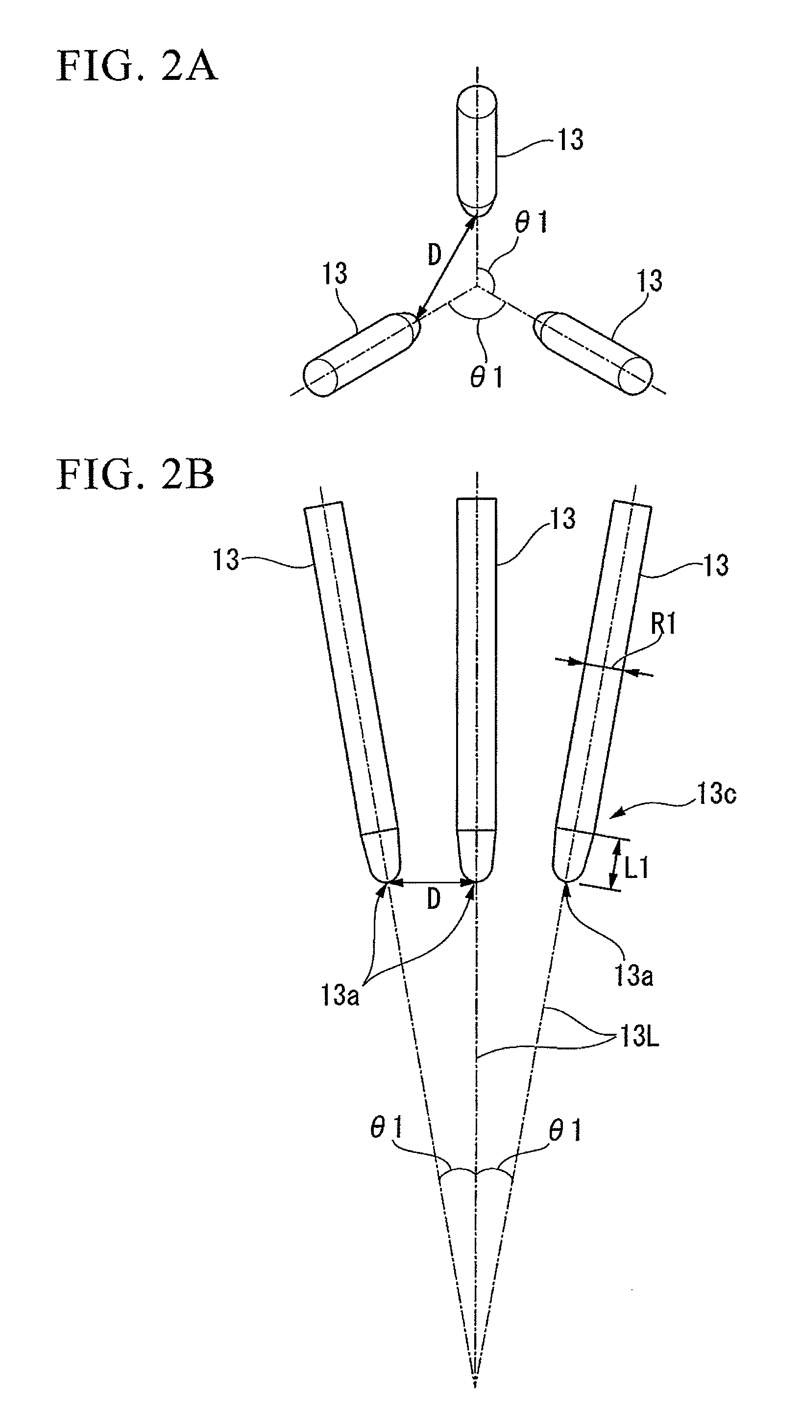
[0137]Fused silica crucibles having a diameter of 32 inches were manufactured by accumulating a vitreous silica powder to form an inner peripheral layer from an outer peripheral layer of the crucible in a rotational mold in advance according to rotational molding, employing the electrode configurations of the six three-phase AC electrodes of the invention, the existing three three-phase AC electrodes (Comparative Example 1), and the six six-phase AC electrodes (Comparative Example 2), changing the inter-electrode distances, and heating and melting the vitreous silica powder. The results thereof are shown in Table 1. In the electrode configuration of Comparative Example 1, extension of the electrodes had occurred, that is, frequent arc breakage had occurred in the case of the diameter of 81 mm of the circumference formed by the electrodes, and when the extension of the electrodes was further increased, an arc was not generated. In addition, in the electrode configuration of Comparati...

example 2

[0138]In the manufacturing process of a fused silica crucible based on the rotational molding, for fused silica crucibles having a diameter of 32 inches, the electrode configurations (the diameter of the circumference formed by the arranged electrodes is 243 mm) of the six three-phase AC electrodes (Example) of the invention and the existing six six-phase AC electrodes (Comparative Example 2) were used to generate an arc five times by supplying a power of 1,000 kW for 20 minutes. Then, the stability of the arc was inspected. The results are shown in Table 2. In the electrode configuration of this embodiment, the arc was stable, so that the amount of power used was almost constant at any time. However, in Comparative Example 2, the arc was unstable, and the amount of power used at each time fluctuated significantly.

TABLE 2Arc timesFirstSecondThirdFourthFifthExample (kWh)337335338338338Comparative284317266291322Example 2 (kWh)

example 3

[0139]In the manufacturing process of a fused silica crucible based on the rotational molding, for crucibles having diameters of 22 to 40 inches, the electrode configurations of the six three-phase AC electrodes of the invention, the existing three three-phase AC electrodes (Comparative Example 1), and the existing six six-phase AC electrodes (Comparative Example 2) were used, and the inter-electrode distance was changed, in order to generate an arc by supplying power of 1,000 kW. Then, the stability of the arc was inspected. The results are shown in Table 3.

TABLE 3ExampleComparative Example 1Comparative Example 2Diameter ofDiameter of(six three-phase(three three-phase(six six-phasecruciblecircumferenceelectrodes)electrodes)electrodes)22 inches140 mmArc stable, goodArc is not generatedArc good24 inches152 mmArc stable, goodArc is not generatedArc good26 inches166 mmArc stable, goodArc is not generatedArc slightly unstable28 inches178 mmArc stable, goodArc is not generatedArc slightl...


PUM

PropertyMeasurementUnit
transparentaaaaaaaaaa
diameteraaaaaaaaaa
diameteraaaaaaaaaa

Abstract

A method of manufacturing a fused silica crucible by heating and melting a vitreous silica powder compact shaped into a mold using arc discharge of electrodes arranged around a rotation shaft of the mold, includes the steps of: arranging the electrodes in a ring shape, and setting a ratio W/R of a horizontal distance W between the electrode front end and the surface of the vitreous silica powder compact to a vitreous silica powder compact opening radius R, for at least a predetermined time during arc heating, to be in the range of 0.002 to 0.98.

Description

BACKGROUND OF THE INVENTION[0001]1. Field of the Invention[0002]The present invention relates to a method and an apparatus for manufacturing a fused silica crucible, and the fused silica crucible, and more particularly, a technique using arc melting suitable for manufacturing a large-diameter crucible.[0003]Priority is claimed on Japanese Patent Application No. 2008-244521, filed on Sep. 24, 2008, the content of which is incorporated herein by reference.[0004]2. Description of the Related Art[0005]A method of manufacturing a fused silica crucible by rotational molding is a method of manufacturing a fused silica crucible constituted by a transparent layer on the inside and an opaque layer on the outside by heating and melting a vitreous silica powder accumulated in a rotational mold by arc discharge. An existing configuration of electrodes for forming the arc discharge is disclosed in Japanese Patent No. 3647688 in which three electrodes are used, and an arc (discharge) plasma is for...

Claims


Application Information

Patent Timeline
Patent Type & Authority Applications(United States)
IPC IPC(8): C30B15/10C03B19/09C03B19/06
CPCC03B19/095C30B11/002C30B15/10C30B35/002Y10T117/10Y10T117/1032Y10T117/1024Y10T117/1072Y10T117/1068C03B20/00
Inventor KISHI, HIROSHIFUKUI, MASANORIMORIKAWA, MASAKI
Owner SUMCO CORP
Why Eureka
Try Eureka