

Vacuum activated closed loop system
a closed loop, vacuum technology, applied in the direction of carburetor air, machines/engines, bends, etc., can solve the problems of no means described for removing any pockets of air and/or gas, air tends to accumulate at the top of the structure, and the juhn porous plate does not work, etc., to achieve greater vacuum motor energy extraction, greater pressure differential, and greater airflow through the motor
- Summary
- Abstract
- Description
- Claims
- Application Information
AI Technical Summary
Benefits of technology
Problems solved by technology
Method used
Image

Examples
Embodiment Construction
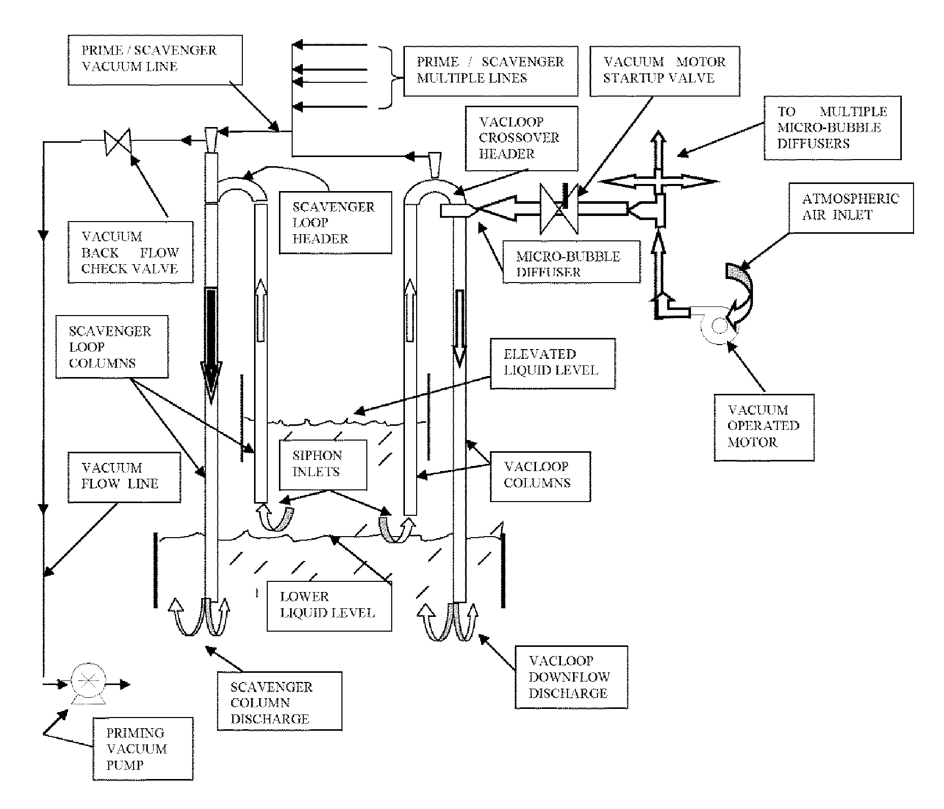
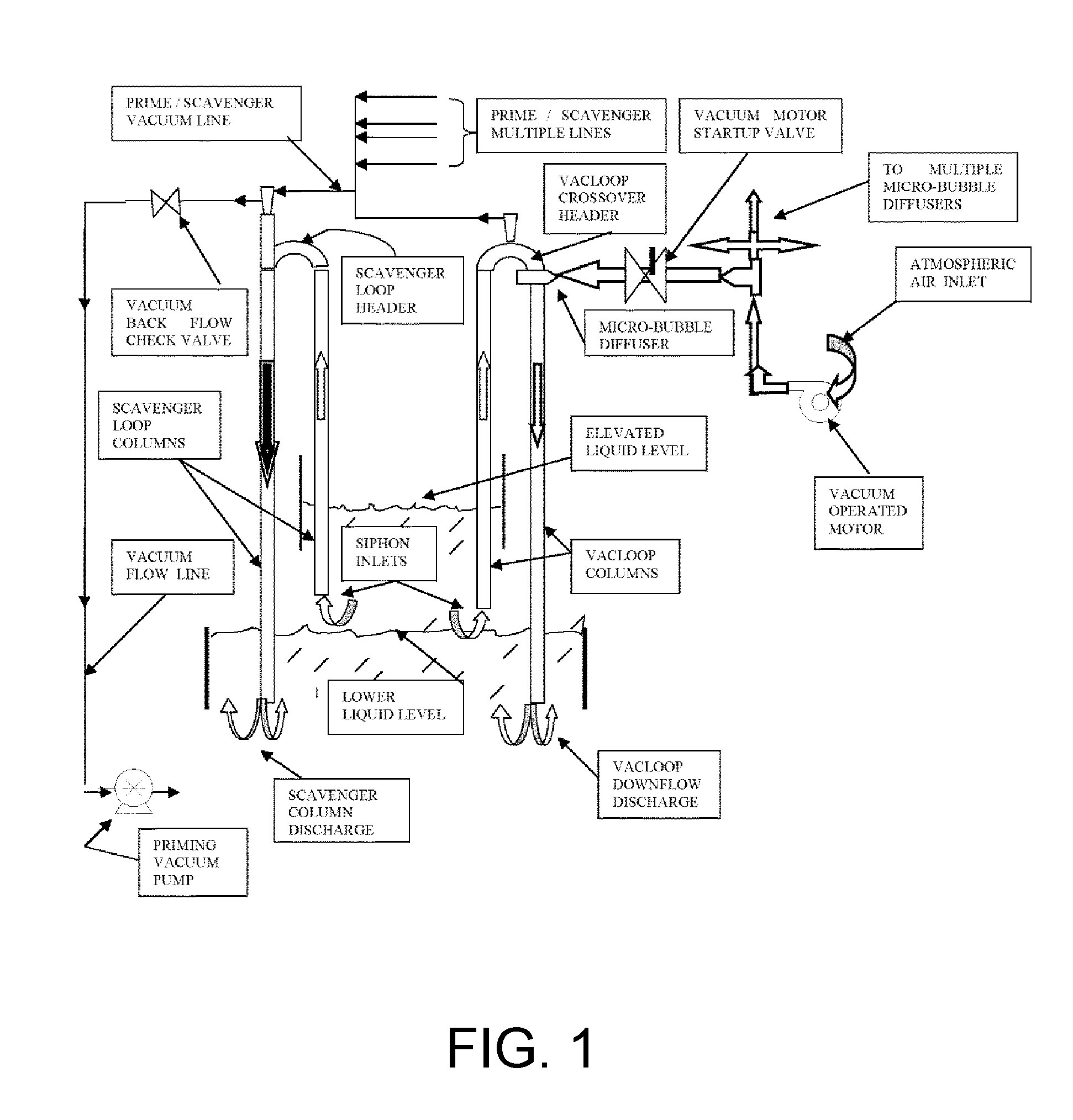
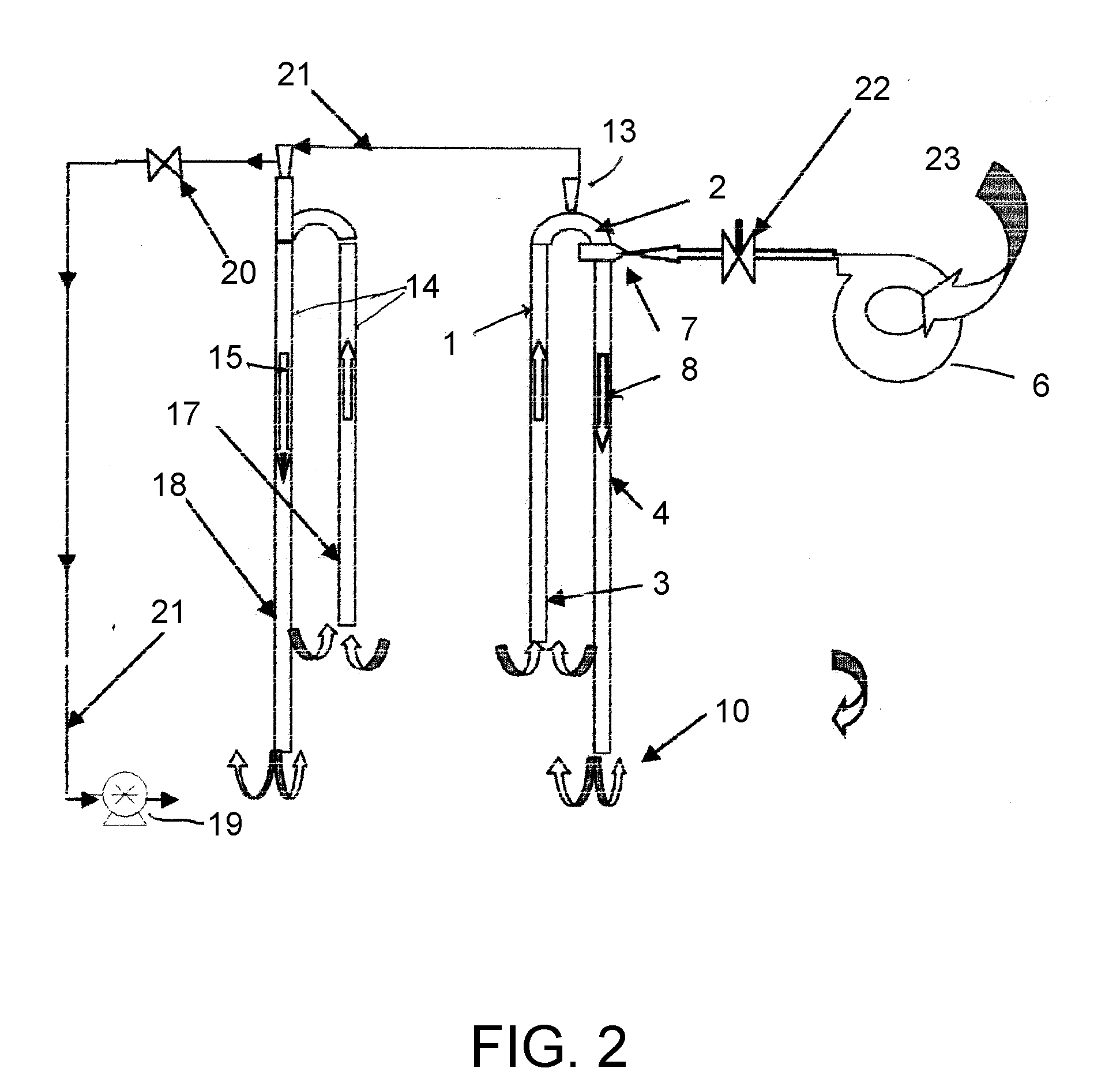
[0018]The Present Invention enables energy to be extracted from the atmosphere by creating a vacuum into which atmospheric air is drawn through a vacuum operated motor. The vacuum is created by water flowing at high speeds through a pipe. The water flows continuously based on the siphon effect. As the water flows past an air inlet positioned perpendicular to the direction of flow, air is drawn into the water column. If a vacuum motor is connected to the air inlet, the rotor spins. A windshield wiper motor is a typical vacuum motor. Energy is then generated by a vacuum motor connected to the air inlet when the vacuum is applied. Vacuum energy is converted therein to mechanical movement via a pivoting piston.
[0019]The Present Invention is fail-safe in that it would shut down from an incident causing loss of vacuum. Residual water would gravity drain. There would be no pressure, water or air related problems. The Present Invention is highly maintainable in that components critical to o...
PUM
 Abstract
Description
Claims
Application Information