

Fuel cell valve and fuel cell system using the valve
a fuel cell valve and valve body technology, applied in the direction of valve operating means/release devices, functional valve types, electrochemical generators, etc., can solve the problems of intensive heat from the heating element and quickly thaw the valve body, and achieve intensive heat and rapid thawing the valve body
- Summary
- Abstract
- Description
- Claims
- Application Information
AI Technical Summary
Benefits of technology
Problems solved by technology
Method used
Image

Examples
Embodiment Construction
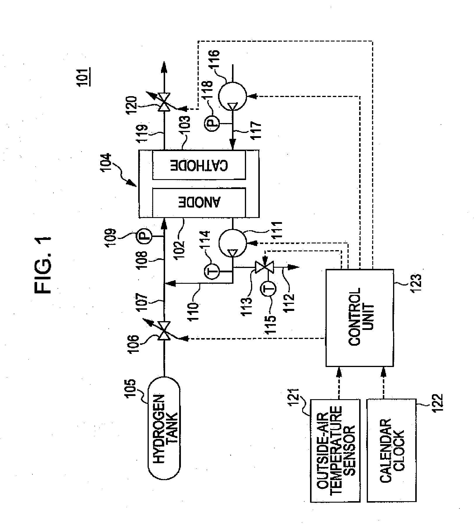
[0019]First, a fuel cell system to which a fuel cell valve according to an embodiment of the present invention is applied will be described with reference to FIG. 1, as a system configuration view. A fuel cell system 101 includes a stack 104 serving as a solid polymer fuel cell body. The stack 104 includes an anode (fuel electrode) 102 to which fuel gas is supplied, and a cathode (oxidant electrode) 103 to which oxidant gas is supplied.
[0020]High-pressure hydrogen gas is stored as fuel gas in a hydrogen tank 105. The pressure of the high-pressure hydrogen gas supplied from the hydrogen tank 105 is reduced to an operating pressure for the fuel cell by a hydrogen pressure control valve 106, and the hydrogen gas is then supplied to the anode 102 via hydrogen supply passages 107 and 108. Part of the hydrogen gas that is not consumed in the anode 102 (anode off gas) is returned to the hydrogen supply passage 108 by a hydrogen circulation passage 110 and a hydrogen circulation pump 111, i...
PUM
 Abstract
Description
Claims
Application Information